Posts

Showing posts from January, 2022

42 lacrosse field diagram

Image
Lacrosse Field Dimensions Diagram Click on Image for Enlarge View Outside Dimensions The exterior measurements of a lacrosse field is 60 yards wide by 110 yards long. Midfield Line The midfield line divides the length of the field in half. Markings on the midfield line include perpendicular markings for the “wing area” Wind Area goal line to the end line. It is not marked on the field. R 30 ft. CENTER CIRCLE 3 0 Y d. R E S T R A I N I N G L I N E (T Y P) 60-70 Yd. FIELD WIDTH 5 Y d. D O T 8 m. ARC 12 m. FAN 1 0-2 0 Y d B E H I N D G L E Not Marked – Representative of theEx nsi Critical Scoring Area DEFENSIVE 1/3 ATTACKING 1/3 PIAA field hockey information such as news, announcements, season schedule, ... Baseball Lacrosse - Girls Lacrosse - Boys Softball. Tennis - Boys Track & Field Volleyball - Boys. ... 2017 NFHS Field Hockey Field Diagram: 8/8/2017: 2017 NFHS Field Hockey Signals: 8/8/2017: 2017 PIAA Field Hockey Game Card: Lacrosse field diagram
40 2006 chevy silverado stereo wiring diagram

Image
Concer.biz Wiring Diagram 2009 Chevy Silverado - Ireleast - Readingrat, size: Listed below is the vehicle specific wiring diagram for your car alarm, remote starter or keyless entry installation into your 2003-2006 Chevrolet Silverado.This information outlines the wires location, color and polarity to help you identify the proper connection ... 2006 Chevy Silverado Trailer Wiring Diagram - A wiring diagram can be a refined traditional pictorial depiction of your electric powered circuit, with its cables and links symbolized as dots. It symbolizes the power circuits elements as simple shapes, with the real power and soil…. 13.01.2016 ... Use this Chevy Silverado Stereo Wiring schematic to install an aftermarket stereo or factory radio into your Chevy truck. 2006 chevy silverado stereo wiring diagram

43 2001 ford focus stereo wiring diagram

Image
2001 Ford Focus Radio Wiring Diagram. Knowing your 2001 Ford Focus radio wire colors makes it easy to change your car stereo. Our 2001 Ford Focus radio wiring guide shows you how to connect car radio wires and helps you when your car radio wires not working. Dec 18, 2020 · 2001 Ford Focus Stereo Wiring Diagram. Print the wiring diagram off in addition to use highlighters to trace the routine. When you make use of your finger or even stick to the circuit together with your eyes, it is easy to mistrace the circuit. A single trick that We use is to print out a similar wiring picture off twice. Dec 23, 2015 · The Ford Focus car wiring diagram listed on this page can help you enjoy your new or used radio, instead of wasting time looking up the wiring for your Focus As stated earlier if you are installing a new or aftermarket stereo into your Focus, you will need a install kit like the one shown above. 2001 ford focus stereo wiring diagram

39 third brake light wiring diagram

Image
3rd brake light wiring diagram? Jump to Latest Follow 1 - 14 of 14 Posts. goldwing1951 · Registered. Joined Feb 2, 2017 · 72 Posts . Discussion Starter · #1 · Mar 23, 2017. Does anyone have the wiring diagram for the 3rd brake light that they can share with me? ... 35 Unique Third Brake Light Wiring Diagram- varying or installing a fresh fixture can be as easy and secure as changing a bulb if curtains properly. Many people are afraid of electricity because they straightforwardly pull off not know tolerable roughly electricity or how it functions. behind a few well instructor simple rules it can keep you a ... J83 said: ^^^ this, the brake light should be 3 wires. 1 will be running light, 1 will be ground 1 will be brake light, meter to verify. Click to expand... The only issue with that is the brake light is combined with the turn signal. So if I tap into that wire, the 3rd brake light will flash with the turn signal. 2009 Chevy 2500 HD LT Z71 CCSB. Third brake light wiring

41 2008 silverado wiring diagram

Image
Fuse box diagram (fuse layout), location and assignment of fuses and relays Chevrolet Silverado, GMC Sierra 1500, 2500HD, 3500HD (2007-2013). Get the best deals for an aftermarket 2008 Chevrolet Silverado 1500 Wiring Harness replacement. Fast shipping with low price guarantee. Order online today! Jan 04, 2021 · Chevrolet Silverado (2007 – 2013) – fuse box diagram. Year of production: 2007, 2008, 2009, 2010, 2011, 2012, 2013. Passenger Compartment Fuse Box 2008 silverado wiring diagram

41 stihl ms 170 throttle linkage diagram

Image
Марка CARVER CHAMPION DOLMAR Dongfeng ECHO EFCO EUROLUX FORZA Foton HONDA HUTER Husqvarna Jinma LIFAN Lovol MAKITA MaxPiler McCULLOCH Oleo-Mac P.I.T. (PIT) PARTNER RAGE REBIR SHINDAIWA STANLEY STERWINS STIHL Shifeng Taishan VIKING Xingtai... Ms 170, ms 170 C, ms 180, ms 180 C... Page 6 (on machines so equipped). If engine is still hot - the fuel may spill over Clean plastic parts with a cloth. 17 Spark plug boot 18 Starter grip 19 Master control lever 20 Fuel filler cap 21 Throttle trigger 22 Throttle lever lock 23 Rear handle 24 Rear hand... I need a little help /r/chainsaw. A few weeks back I posted about some self inflicted damage I did to my saw. I was moving too fast as I was getting work lined up and I left my saw idling in half choke with the brake on. The saw overheated and the damage was as follows: -clutch drum/needle bearing shot -brake band twisted - plastic melted around clutch/drum I ended up replacing the clutch, oil pump, needle bearing, drum, brake band and t

42 chainsaw ignition coil wiring diagram

Image
Stihl MS 290 Chainsaw (MS290) Parts Diagram, Ignition system. Look at the diagram and find parts that fit a Stihl MS 290 Chainsaw, or refer to the list below. Carb. HD-18B-HD-21B (only USA) Mar 26, 2020 · Video: How to Test a Chainsaw Ignition Coil with a Multimeter. On-off wires (breaker) and a cable (armored wire) are mounted from the module (coil), mounted in the cap, where the glow plug is inserted. The on-off wires have a small cross section, in contrast to the candle cable, along which high voltage moves. Makita chainsaw ignition coil replacement. Read full answer. Be the first to answer Sep 05, 2013 • Garden. 0 answers. Wiring diagram for ignition coil on 025 stihl. Read full answer. Be the first to answer Aug 09, 2013 • Cars & Trucks. 0 answers. Chainsaw ignition coil wiring diagram

39 crown victoria wiring diagram

Image
Jul 22, 2020 · 4.6L Flex Fuel, Engine Performance Wiring Diagram (3 of 6) for Ford Crown Victoria Police Interceptor 2011. Get Access all wiring diagrams car. Jul 22, 2020 · 4.6L Flex Fuel, Engine Performance Wiring Diagram (3 of 6) for Ford Crown Victoria 2008. Get Access all wiring diagrams car. "2006 Crown Victoria/Grand Marquis Wiring Diagrams" Written for Ford dealership mechanics, this factory-published original wiring diagram shows you how to follow the wiring from bumper-to-bumper. It will help you understand connector configurations, and locate and identify circuits, relays, and grounds. Crown victoria wiring diagram

43 2007 dodge ram stereo wiring diagram

Image
77 Elegant 2012 Dodge Ram Radio Wiring Diagram- Car radio installation trimmings comprise of harness adapters leads, fascia adapters, stalk/steering wheel direct adapters (also known as smart leads) and aerial adapters. 2010 Dodge Grand Caravan Radio Wiring Diagram SchemaDodge Ram 1500 Wiring Diagram Wiring Diagrams BlogOne or more of the above adaptors may be needed like you are installing an ... Dodge Ram Radio Wiring Diagram In 2021 Dodge Dakota Diagram Dodge . It is the same manual that your local dodge dealer mechanics use to diagnose and repair your car. Schematic dodge ram 1500 wiring diagram free. A wiring diagram is a streamlined standard photographic representation of an electrical circuit. 2007 Dodge Ram 3500 Radio Wiring Diagram. Knowing your 2007 Dodge Ram 3500 radio wire colors makes it easy to change your car stereo. Our 2007 Dodge Ram 3500 radio wiring guide shows you how to connect car radio wires and helps you when your car radio wires not working. 2007 do

43 reversing solenoid wiring diagram

Image
Reversing Solenoid Relay 6 Terminal Trombetta Winch Windlass Slideout 12v Com. Relay Diagram For Switching Polarity. 12v 6 Terminals Electrical Winch Solenoid Contactor Relay For Reversible Motors. 12 volt dc reversing solenoid 12vdc 6 post winch 100 amp polarity 24450 cole hersee motor dc66 9p 80a leroy somer windlass usvi battery disconnect ... 12 Volt DC Polarity Reversing Solenoid For Permanent Magnet Motors Trombetta 1306600, DC Relays Contactors & Solenoids, 12 VDC REVERSING SOLENOID FORTrombetta,1306600 , Surplus 0. my ... Wiring Diagram. Ask A Question. ASK A QUESTION. Submit a question for this product Showing Questions of 1. The solenoid locks out the coupler, allowing you to back up the trailer without the brakes actuating. If you are using a 5-pole connector, the blue wire from the connector would tap into the reverse light circuit. I have provided a diagram that should help illustrate this for you. Reversing solenoid wiring diagram

38 occupancy sensor wiring diagram 3-way

Image
spectraplot disclaims all liability to any party for any direct, indirect, special, consequential or other damages in connection with any use of this website, or any hyper-linked Wireless networks are faster than wired networks. However, the average upload speed of the Unifi AP LR is 19.21…about 10 Mbps less than the hard wired internet speed test. Most When using in a 3-way application use one sensor and one standard 3-way switch. Cannot be used with another ... Connect wires per WIRING DIAGRAM as follows:. Occupancy sensor wiring diagram 3-way

39 1996 ford f150 fuse box diagram

Image
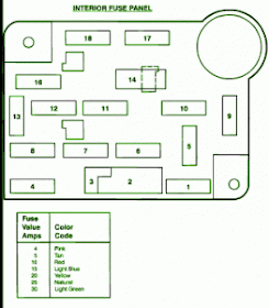
The 1996 Eddie Bauer Special Ford F-150 has 2 different fuse boxes: Instrument Panel Fuse Panel diagram. Engine Compartment Fuse Box (GASOLINE) diagram. * Ford F-150 fuse box diagrams change across years, pick the right year of your vehicle: Under-Hood Fuse/Relay Box (1996 Ford F150, F250, F350) Locations and descriptions of the fuses and relays of the under-hood fuse/relay box for 1996 Ford F150, F250 and F350 (gasoline engine only). The under-hood fuse/relay box is known as the Power Distribution Center in the Ford service/repair literature. You can find the under-hood fuse/relay ... fuse box diagram (1994-1997) — The fuse panel is located on the instrumen panel behind acces door, to the left of the steering column. fuse box layout 1992- ... 1996 ford f150 fuse box diagram

42 bryant furnace wiring diagram

Image
Bryant GAS-FIRED INDUCED-COMBUSTION FURNACES 373LAV User Manual • Fig. 12—furnace wiring diagram • Bryant Kiln. Visit www.bryant.com ... S The furnace is permanently installed with all electrical wiring, ... 32 -- Heating and Cooling Application Wiring Diagram. Feb 27, 2004 · Gas and Oil Home Heating Furnaces - Wiring diagram for thermostat for a Bryant Electric furnace - I just got a Bryant electric furnace Model # 962-024-010-A serial # 12C43363. I have a new standard thermostat that I want to install. However, I do not have wiring diagram with furnace so I know what goes where. I know Bryant furnace wiring diagram

43 2005 gmc sierra brake line diagram

Image
My dad has a 2005 Sierra the front brakes keep trying to lock up or atleast they don't want to relax after hitting the brakes. If you hit the brakes real hard they'll loosen back up till the next time hit the brakes. We've replaced all the hoses, calipers, pads, rotars, master cylinder, everything I can think of unless it has to do with the pedal sticking any. Also the abs light hasn't came on so I don't think has anything to do with that. Just wondering if anybody else has had any problems or a... Equip cars, trucks & SUVs with 2005 GMC Sierra 1500 Master Cylinder (Brake System) from AutoZone. Get Yours Today! We have the best products at the right price. We currently carry 12 Brake Line products to choose from for your 2005 GMC Sierra 1500, and our inventory prices range from as little as $99.59 up to $134.99. On top of low prices, Advance Auto Parts offers 2 different trusted brands of Brake Line products for the 2005 GMC Sierra 1500. We only sell p

42 classic instruments wiring diagram

Image
a. Black wire from a Classic Instruments signal generator b. Ground of a SN74 speedometer calibration box 7) Connect the speed signal power to the "B+" or "1" terminal on the back of the speedometer: a. Red wire from a Classic Instruments signal generator b. Power of a SN74 speedometer calibration box Working on Classic cars can sometimes be a bit tricky. Replacing a part, might seem easy enough but there are almost always other parts need to complete the job. That’s where our Classic Mini Exploded Diagram Catalog comes in handy. SN38T*. *Represents size of tube length (1" increments) from bottom of mounting flange. Allow at least 1/4" clearance from end of tube to bottom of tank. Please call for availability for length before ordering. Some sizes my take up to two weeks to build then ship. 1-800-575-0461. WARNING: This product can expose you to Lead which is known to ... Classic instruments wiring diagram

42 scotts riding lawn mower belt diagram

Image
Scotts Riding Mower Belt Diagram 42 Inch. Garden product manuals and free pdf instructions. Find the user manual you need for your lawn and garden product and more at ManualsOnline. If the belt that drives the blades on your Scotts S lawn mower is slipping, it's time to Decks that are inch have one belt guard and two cap screws. Hi,I need a drive belt routing diagram for a Scotts (made by John Deere) lawmmower. It is a model Scotts H with a Kohler 16 hp OHV 1. If the belt that drives the blades on your Scotts S lawn mower is slipping, it's time to replace it. Worn belts stretch and don't make sufficient contact with the. Scotts S1742 (Deck 42") Riding Lawn Mower Replacement Belt Original Equipment Manufacturer Scotts OEM Part Number M124895 Machine Riding Lawn Mower Model S1742 (Deck 42") Belt Type 4LK/AK Aramid VBG Replacement Id APPL673762 Technical Specifications: (Inches) (mm) Outside Circumference 115.00 2921.00 Top Width 0.50 12.70 Belt Depth 0.312

43 lincoln mig welder parts diagram

Image
Edit: I have 0.9 mm Innershield NR-211-MP-RSP wire WELD-PAK 100. NOTE: This Parts Manual is provided as an informative guide only, when ordering parts always refer to the Lincoln. Electric Parts List. MIG welders are the best introductory tool for welding. They are easy to use and can be mastered with practice and work. Patrick Foto/Moment/Getty Images If you're thinking about getting into welding, you have to ask yourself what type of w... Lincoln mig welder parts diagram

43 2008 bmw x5 fuse box diagram

Image
BMW X5 E70 crossover was produced in 2007, 2008, 2009, 2010, 2011, 2012 and 2013. During this period, the E70 received one restyling.F171: (100A)‎Passenger compartment · ‎Luggage compartment · ‎Main fuse box 2008 bmw x5 fuse box diagram

38 2003 ford ranger radio wiring diagram

Image
2003 ford Escape Radio Wiring Diagram | Free Wiring Diagram Variety of ford escape wiring diagram. A wiring diagram is a streamlined traditional pictorial representation of an electrical circuit. It shows the elements of the circuit as streamlined forms, and the power as well as signal connections in between the gadgets. ... 2001-2003 Ford Ranger Wiring Diagram. Printer Friendly. Version. Listed below is the vehicle specific wiring diagram for your car alarm, remote starter or keyless entry installation into your 2001-2003 Ford Ranger . This information outlines the wires location, color and polarity to help you identify the proper connection spots in the vehicle. Please be sure to test all of your wires with a digital multimeter before making any connections. 2003 Ford Ranger Radio Wiring Diagram. Knowing your 2003 Ford Ranger radio wire colors makes it easy to change your car stereo. Our 2003 Ford Ranger radio wiring guide shows you how to connect car radio wires and helps

42 pig body parts diagram

Image
Guinea Pig Anatomy A Guinea Pig is a small, burrowing rodent that has a compact body. Guinea pigs have small ears and eyes, a small snout with sensory whiskers each side and no tail. Like most rodents, they have two gnawing teeth at the front which continue to grow throughout their life. Because these teeth […] Data are percentage of total body weight. Species Water Protein Fat Human, newborn 69.1 11.9 16.1 Rat, newborn 86.0 10.8 1.1 Pig, newborn 84.1 11.3 1.1 Pig, 7 days old 68.5 13.6 9.5 Pig, 28 days old 61.8 14.4 17.8 From Widdowson, 1950 and Manners and McCrea, 1963. Table 2. Common blood collection tubes (tubes with * are commonly used) Image 1: Fetal Pig 3. Examine the pig for body hair, although this is usually not conspicuous currently. Is body hair present? a. Look under the chin for some longer hairs. 4. Note the epitrichium, the layer of embryonic skin that is visibly peeling. This is lost as the hair develops. It may be removed by rinsing the pig in tap water. Use

42 ford f150 engine diagram

Image
Access Free 98 Ford F150 V6 Engine Diagram materials, electronics and controls, and aerodynamics. And by 2030, the deployment of alternative methods to propel and fuel vehicles and alternative modes of transportation, including autonomous vehicles, will be well underway. Original factory workshop service and repair manual of 2011-2014 Ford F-150 with wiring diagrams, body repair manual and owner's manual. It is the same manual that your local Ford dealer technicians use to diagnose and repair your Ford.. OEM Service and Repair Manual of 2011-2014 Ford F-150 covers the following engines:- Ford Lightning. Ford F150 Lariat. Car Ecu. Line Diagram. Truck Repair. 1983 Ford Bronco Diagrams picture. pcvefis.jpg PCV Hoses for EFI engines, EXCEPT MAF IF THE IMAGE IS TOO SMALL, click it. The rubber hose connecting the hard plastic PCV vent tube (F5TE6C324AA) to the nipple on the oil filler neck of the valve cover can be replaced with [url ... Ford f150 engine diagram

38 5r55e valve body diagram

Image
Ford 5R55S, 5R55W Valve Body Layout. Sonnax valve body layouts provide a detailed overview of individual units making it quick and easy to determine what's available for the specific valve body you're working on. Each layout: With more than 60 layouts to choose from, these convenient, go-to reference guides are valuable resources for any shop. 4R44E Shift Kit Installation, on this video we will see the upgrades that can be done to this valve body with, or without the purchase of a shift kit. We wil... Valve Body Alignment Pins and Center Support Bolt Torque center support bolt to 8 lb. ft. Alignment pin Alignment pin Use Ford alignment pins #307-334 at locations shown. 28 A pump puller is necessary to remove the pump. Torque pump bolts to 18 lb. ft. Pump Assembly . 29 5r55e valve body diagram

41 mazda 6 headlight assembly diagram

Image
You like your Mazda 6 because it is an economical sports car that delivers a lot of power and good looks from a 4-cylinder engine. When you are ready to do your regular maintenance on your 6, you want to ensure that the parts you use are factory parts built just to fit your car. Anonymous. 41 Answers. SOURCE: need to change headlight on 2003 mazda rx 6. If it is the headlight itself. There may be a cover or shroud on the front of the engin bay. Remove that, may be a combination of clips and screws. If it does not cever the light area, it is even easier. There will probably be 3 screws or nuts, remover these and unplug ... Parts & Tools Full list of part and tools. Video Description The video above shows you to replace the headlight in your 2010 Mazda 6. Headlights grow dimmer by up to 20% over time and eventually burn out - for this reason, we recommend changing your headlights in pairs. Changing both headlight bulbs on your 6 at the same time will allow both ... Mazda

40 class diagram visio

Image
Hi All, Recently, I purchase a Visio 2013 Pro. I have used Visio 2010 before. In Visio 2013, Compared with Visio 2010, There are BIG changes in Visio 2013. I have several questions for Visio 2013. 1. I don't know how to set in/out parameter in Visio 2013 class diagram. 2. How to set parameter ... · This functionality (model building) was removed in ... Draw class diagrams online with Creately. Online class diagram tool with class diagram templates including examples for other UML diagrams. Industry-standard class diagram shape library and advanced drawing features to create class diagrams quickly. When it comes to system construction, a class diagram is the most widely used diagram. UML Class Diagrams is a type of static structure diagram that is used for general conceptual modeling of the systematics of the application. Such a diagram would illustrate the object-oriented view of a system. The object orientation of a system is indicated by a class diagram. Class diagram

42 parts of a folding knife diagram

Image
Antique Manicure Tool - 9 images - condor tool knife ctk1019 32hc grosse messer sword, bark river knives bravo 1 5 fixed 5 8 a2 tool steel blade, MOUNTAINS Mount Olympus is in Greece. The mountain range in Russia that is regarded as the boundary b/w Europe & Asia is Urals. Margalla Hills of Islamabad are extensi Parts of a folding knife diagram

43 2.4 ecotec timing chain diagram

Image
Jun 4, 2016 - This 2010 Chevrolet Equinox came in because it was overheating. I removed the water pump access cover and i could spin the water pump with my ... Hi, I'm doing a headgasket job on a 2011 chevy equinox, I'm assembling the timing portion of it and every time I get the cams and crank in time and go to rotate the engine timing chain jumps teeth. I am replacing the timing chain, timing chain tensioner, and all 3 timing chain guides. I have tried following multiple videos on this engine and it keeps jumping teeth, am I missing something? Ecotec Timing Chain Guide Bolt. This aftermarket piece replaces the plagued stepped shoulder bolt that has a high tendency of breaking in the Ecotec 2.0, 2.2, 2.4 liter GM engine. It is far superior in every way and will not require you to replace the head that can be damaged when the factory bolt breaks. An absolute must have for every GM ... 2.4 ecotec timing chain diagram

43 transmission line diagram

Image
Nov 13, 2015 · A typical layout of a generating, transmission and distribution network of a large system would be made up of elements as shown by a single-line diagram of Figure 1 although it has to be realized that one or more of these elements may be missing in any particular system. For example, in a certain system, there may be no secondary transmission and in another case, when the generating station is nearby, there may be no transmission and the distribution system proper may begin at the generator ... Single Line Diagram: In single line representation of power system, the components of the system are represented by standard symbols & the transmission lines are represented by straight lines. ³Hence a single line diagram is diagrammatic of power system in which the components are Dec 03, 2018 · What is a Single Line Diagram? A Single Line Diagram or a One Line Diagram is a simple way to draw the Electrical Circuit in a Power System. By adopting this Electrical Line

41 2008 chevy silverado radio wiring diagram

Image
2008 Chevrolet Silverado Wiring Diagram from ww2.justanswer.com. Print the wiring diagram off plus use highlighters to trace the signal. When you make use of your finger or perhaps the actual circuit with your eyes, it is easy to mistrace the circuit. 1 trick that We 2 to printing a similar wiring plan off twice. SOURCE: I need a wiring diagram for a 1989 chevy silverado. When I replace a stereo, I buy the harness which is available on Ebay.com or places like Best Buy. All of the wires are labeled and color coded which makes it easier to connect with the wire nuts to any aftermarket stereo that fits in your dash. Posted on Aug 03, 2010 2008 Chevy Silverado Radio Wiring Diagram. Assortment of 2008 chevy silverado radio wiring diagram. A wiring diagram is a streamlined standard photographic representation of an electrical circuit. It reveals the elements of the circuit as streamlined shapes, and the power as well as signal links in between the devices. A wiring diagram typicall

43 diagram of electric motor

Image
Baldor Motor Wiring Diagram - baldor 5hp motor wiring diagram, baldor brake motor wiring diagram, baldor dc motor wiring diagram, Every electrical structure is composed of various diverse parts. Each component should be set and connected with different parts in particular way. If not, the arrangement will not function as it should be. Electric Motor Wiring Diagram from www.electricmotorwarehouse.com Print the wiring diagram off plus use highlighters to trace the signal. When you make use of your finger or perhaps the actual circuit with your eyes, it is easy to mistrace the circuit. 1 trick that We 2 to printing a similar wiring plan off twice. (a) An electric motor converts mechanical energy into electrical energy. View Answer NCERT Question 11 - Draw a labelled diagram of an electric motor. Explain its principle and working. What is the function of a split ring in an electric motor? View Answer NCERT Question 12 - Name some devices in which electric motors are used. View An

43 wu tang clan 8 diagram

Image
GZA is an original member of the legendary Wu-Tang Clan. GZA's contributions have driven the phenomenal success of the 2008 Wu-Tang Clan reunion album ";8 Diagrams" as well as two of independent Hip Hop's flagship releases: "Think Differently Music: Wu-Tang Meets The Indie Culture" and the DJ Muggz/GZA collaboration "Grandmasters" (both having ... Upptäck Wu-Tang Clan's artistprofil på Musicstax och upptäck deras topplåtar, BPM och mer. lego duplo train motor positano leather sofa the money store album cover the money store album cover Wu tang clan 8 diagram

40 molecular orbital diagram f2

Image
Jan 15, 2022 · A molecular orbital diagram, or MO diagram, is a qualitative descriptive tool explaining chemical bonding in molecules in terms of molecular orbital theory ... 29 Sept 2017 — Fluorine molecule is formed by the combination of atomic orbitals of two fluorine atoms, each having nine electrons, thus making 18 electrons.2 answers · 62 votes: O2 and F2 is an execption so their Z shell is down ... Relationship between electronic configuration and Molecular behaviour. 1) Stability of molecules in terms of bonding and antibonding electrons . Number of electrons present in the bonding orbitals is represented by N b and the number of electrons present in antibonding orbitals by Na.. 1) If N b > Na,the molecule is stable because greater number of bonding orbitals are occupied than ... The molecular orbital diagrams for molecules and ions are drawn from the order of increasing energies shown in the molecular orbital configuration. Always remember that the number of molec

40 vacuum line diagram for chevy 350

Image
Save my name, email, and website in this browser for the next time I comment. ... 1978 Chevy 350 Vacuum Lines Diagram Looking to find someone with a comparable G30 or knowhow to figure out how to reconnect my vacuum resevoir(black ball on the hood). I can only get air to blow out the defroster, and I've narrowed it down to the vacuum resevoir being disconnected, but I can't find any diagrams to get it back together. Diagram 1990 Chevy Suburban 2500 Engine Diagram Rtu Wiring Diagrams , 96 S10 2 2 Wiring Diagram , On Off On Toggle Switch Wiring Diagram 24 Volts , ... Vacuum line diagram for chevy 350

43 race car push button start wiring diagram

Image
The home electrical wiring diagrams start from this main plan of an actual home which was recently wired and is in the final stages. To get more knowledge about them one can search Google using. Identify any special wiring needs by room: Residential electric wiring diagrams residential from home electrical wiring plan. If you are just using the push button switch as a temporary fix, you don't have to actually install it. 35 Lovely Push Button Starter Wiring Diagram Diagram Wire Electrical Wiring Diagram . How To Convert Car To Push Button Start . Push Button Start Switch - Red Illuminated Johnnylawmotorscom Keep It Cleaner Buttons Push To wire this as a master switch and start button ideally youd cut the power to the VT-GN wire on the output of the master switch when you push the start button. Push Button Starter Switch Wiring Diagram Circuit Using 11N Push Button Starter Switch Wiring Diagram. The starter solenoid usually has two small terminals and two large terminals.

38 2006 toyota avalon serpentine belt diagram

Image
My cars alternator crapped out on me a few weeks ago and left me stranded. I towed it to a repair shop and they replaced the alternator. The car is driving fine now, but a couple of days ago I noticed a clicking noise going on under the hood that gets louder whenever you hit the acceleration pedal. The longer the car runs the less the noise happens. ​ Does this seem like I got a bunk Alternator, or that one of the belts needs to be replaced? Link below contains video/sound I'm hearing. I know... So I did a oil change on my Saab 9-5 (engine B235E) I found seeping around the serpentine belt area. Wanting a detailed list of each pulley does what with labels. Also for fun found oil intake. So I might do a PCV replacement. The serpentine belt on my 2006 Toyota Corolla has been making a chirping sound when the car is running (it gets worse when accelerating) despite multiple trips to the mechanic. Here are things that have gone on in the past several months: - My car wouldn’t s

42 snorkel lift wiring diagram

Image
specs, operator's parts & service manuals - snorkel lifts snorkel atb60 lift troubleshooting, diagnostics - snorkel lift model uno 41 parts manual | pdf snorkel lift manuals pdf snorkel lifts & snorkel aerial work platforms atb 38e snorkel lift wiring diagram | tricia joy epw- parts for aerial lift equipment - genie, jlg Related handgun ... Snorkel Scissor Lift Wiring Diagram . November 20, 2020 1 Margaret Byrd . 0 . Snorkel sl20 sn9300 user manual page manualzz operator s pdf repair parts manufactured 02 01 s1930 manuals manualslib s3246 ce 60 pages board replacement tips by c tech danger s3219e 7348000653 case genie jlg ... Quickly gain interactive access with free downloads of all Snorkel parts and service manuals, hydraulic and electric schematics, product bulletins, recommended spare parts lists, and more from The Platform™, a 24/7 online system. To access the online manual libraries, please click here. If you need assistance to locate a Snorkel manual, pleas

40 stihl 028 parts diagram

Image
STIHL. STIHL was founded in 1926 by Andreas Stihl, who built the first chainsaw. The company has since expanded to offer many other power and hand tools for home and numerous industries. While they are headquartered in Germany, the company also maintains warehouses, factories, and administration buildings in the states. Stihl 044 magnum specs [email protected] rpm (5,5 [email protected] rpm reported when tested by DIN Follow Us: To identify the model number on a Stihl chainsaw, locate the nine-digit serial number that is stamped into the motor housing or crankcase, and then reference the owner's manual or contact the manufacturer for additional details Internal combustion engines can contain any number of combustion chambers (cylinders), with numbers between one and twelve being common, though as many as 36 (Lycoming R-7755) have been used.Having more cylinders in an engine yields two potential benefits: first, the engine can have a larger displacement with smaller indivi

43 72 c10 wiring diagram

Image
67 72 c10 instrument cluster wiring diagram. 1981 el camino dash. Take A Sneak Peak At The Movies Coming Out This Week 812 Emmy 2021 Winners. 67-72 C10 Extreme Series Chassis. A b f71 15a. Power distribution frc 12 wiring diagram. Aa spf44a spx03ea3 fb2a1-08 ag0 b a17b2 ai4 c frc_j3c5 aq1 b mcsca9 f61a1-08 hb2 d a131ba4 f15a1-50 bi3 c x210aad ... Instrument Cluster Wiring 1) Always disconnect the vehicle battery before wiring any gauge. 2) Connect a good chassis ground to the Black [Position 1] wire of the gauge cluster harness. We recommend using a dedicated chassis ground (not stacked with other ground wires) to avoid possible problems caused by a bad ground. 1967-72 Chevy truck V8 and cab wiring. This is a GM diagram that I colored using Photoshop. Please download the largest size and use it and share it. 72 c10 wiring diagram

43 honda civic engine mount diagram

Image
Brian Eslick from How to Automotive http://www.howtoautomotive.com takes you step-by-step through the process of replacing the front engine mount on a 2007 H... 20/10/2015 · Description: Honda Civic 4 Door Lx Ka 4At A/c Hoses – Pipes inside Honda Civic 1998 Engine Diagram, image size 1108 X 553 px, and to view image details please click the image.. Here is a picture gallery about honda civic 1998 engine diagram complete with the description of the image, please find the image you need. 27/03/2016 · Description: Honda Civic 2 Door Lx Ka 5Mt Engine Mounts (1.8L) with 2012 Honda Civic Parts Diagram, image size 1108 X 553 px Description : 2012 Honda Civic 4 Door Lx Kl 5At Front Grille – Hondapartsnow inside 2012 Honda Civic Parts Diagram, image size 1108 X 553 px, and to view image details please click the image. Honda civic engine mount diagram

40 romeo and juliet plot diagram

Image
Plot Structure And Characterization Plot Structure High School Reading Plot Anchor Chart. Break Down Shakespeare S Five Act Structure Using A Romeo And Juliet Storyboard Created On Storyboard That Romeo And Juliet Shakespeare Lessons Plot Diagram. Structure Of Shakesperean Tragedy Shakespearean Tragedy Tragic Hero Hero Essay. Dec 13, 2013 · Romeo and Juliet Plot Diagram by: Sara-Lynn Makekau Climax: English, Period Two Yellow Kumaewa/Dumapit Juliet is told that she will be married to Paris on Thursday and she becomes very defiant. She starts to lose trust in her confidant, the Nurse, because she wants her to marry Plot Structure of Romeo and Juliet - Free download as Powerpoint Presentation (.ppt), PDF File (.pdf) or view presentation slides online. Plot Structure of Romeo and Juliet Exposition: Romeo shows his lust for Rosaline; normal conversations in Montague and Capulet families; Mercutio makes fun of Romeo because of Rosaline's intent to never marry. Romeo and juli

43 2002 ford explorer radiator diagram

Image
110 Answers. Re: Where can i find a diagram for replacing the... You can look online on ford.com. But here it is. Remove the cover over the radiator. Open drain down on bottom. Remove hoses connected to the radiator. Use a wrench to remove the transmission fluid lines. Remove the bolts holding the radiator/fan cover and slide it towards the fan. Pertaining to 2002 Ford Explorer Engine Diagram image size 430 X 360 px and to view image details please click the image. In our wide assortment of Ford Explorer engine cooling parts you can find water pumps cooling system switches oil coolers radiator hoses coolant overflow tanks and many other components. 21 14 x 24 x 1 14. SOURCE: how to remove 2002 ford taurus radiator Remove the rad support cover, remove the electric cooling fan and shroud, disconnect the tranny cooler lines, drain the cooling system, remove the upper and lower hoses, remove the rad brackets on top of the rad (one on each side), have someone hold the AC core out

43 1999 chevy suburban rear brake diagram

Image
Door & Components for 1999 Chevrolet Suburban K1500. 1. $381.75. Door Shell Dual swing type. $391.35. Door Shell Dual swing type. Brake Controller Installation on a 1999 Chevy C3500 Pickup Truck Recommended Brake Controller and Wiring Adapter for a 2001 Chevy Tahoe Installing a Brake Controller on a 2001 GMC Sierra 1500 with Factory 7-Way Trailer Connector Apr 14, 2010 · 100 Answers. Re: I need a diagram for the rear brakes of a 1999 GMC... Go to carhelpsite.com it is free as long as you click on 2 of the ads at the website then your questions will be answered by an ASE certified mechanic,you don't have to buy or fill out anything on the ads,so help keep the site free. Posted on Apr 14, 2010. 1999 chevy suburban rear brake diagram

38 grote turn signal switch wiring diagram

Image
Grote Industries - Part: #48072 - Universal 7-Wire 4-Wire Turn Signal ... Bulb: (Indicator) 53, 1 CP; VMRS: 034-003-016; # of Wires: 7; Style: Universal ... Please see the wiring diagram on the product page for this product. I'm installing a 48532 turn signal switch and need an installation diagram or wiring diagram For a 48532. Grote's Answer. The mounting and installation ... Grote turn signal switch wiring diagram

42 free body diagram of circular motion

Image
The correct free-body diagram is diagram 3, which shows only the force of gravity applied by the Sun on the Earth. The word "centripetal" means "directed toward the center." When an object experiences uniform circular motion, the object has a centripetal acceleration directed toward the center of the circle. Students can draw free-body diagrams to illustrate forces acting on a sphere or a coin moving in a uniform circular motion. In each case, they should indicate the force(s) responsible for the centripetal force. The relative length of the vectors corresponding to the forces should be drawn to scale. Symbols: F g— Weight F T— Tension F f— Friction F The free-body diagram in each case consists of only the dark, solid arrows. Forces of the same magnitude or lines of the same length are indicated by the same number of "tick" marks drawn through the two lines or arrows. Free body diagram of circular motion

41 activity on arrow diagram generator

Image
In activity on arrow diagrams, nodes are called events. First node is always the "START" event and last node is the "END" event. On the other hand, in activity on node diagrams, activities are shown on the node. 19.4.1 Dummy Activities. Broken arrows are used to indicate dummy activities. Activity F cannot be started until activities A ... Activity on arrow. The original form of network diagram that has effectively been superseded by the precedence diagram format. In an activity-on-arrow network, activities are represented by a line between two circles. A network diagram is created by connecting activities according to their dependence upon each other. AOA diagram only uses the Finish to Start relationship. It shows the duration on the arrows; therefore, many experts call this diagramming method the activity on arrow diagram. PERT is an example of this technique. There is a difference between the AON and AOA diagrams. Activity on arrow diagram generator

39 metra 70 1721 wiring diagram

Image
Metra 70-1721 Wiring Harness For 1998-2005 Acura/Suzuki/Honda Vehicles from i.ebayimg.com Print the wiring diagram off plus use highlighters to trace the signal. When you make use of your finger or perhaps the actual circuit with your eyes, it is easy to mistrace the circuit. 1 trick that We 2 to printing a similar wiring plan off twice. Metra 70-1721 Radio Wiring Harness for Honda/Acura 98-Up Power 4 Speaker : Amazon.ca: Electronics. Metra 70-1721 Wiring Diagram Buy Metra Wiring Harness for Acura/Suzuki/Honda Vehicles: Radio Wiring Harnesses - diagramweb.net FREE DELIVERY possible on. Metra Receiver Wiring Harness This vehicle-specific wiring harness makes connections between your new car stereo and your cars electrical. Metra 70 1721 wiring diagram

39 mercedes radio wiring diagram

Image
Fitting instructions: radio communication systems. AUDI A1 2011 , ... Audi 5000 s Wiring Diagram download pdf SYSTEM WIRING DIAGRAMS S Audi - 5000 S ... MERCEDES ERROR CODES, ENGINE CODES. DAIHATSU ENGINE TROUBLE CODES … Hello everyone. Does anyone know where I can find a simple wiring diagram for the radio hardness on a 2003 nissan altima? I purchased a radio and adapter but the connections to both are lose and semi stripped wire that I have to connect myself. I don't want to mess the car or my radio up, so is there an easier way to confirm what connects to what? Workshop and Repair manuals, Service & Owner's manual. Wiring Diagrams, Spare Parts Catalogue, Fault codes free download. Free Repair Manuals & Wiring diagrams. Mercedes-Benz Service Manual. Mercedes radio wiring diagram

39 s13 wiring diagram

Image
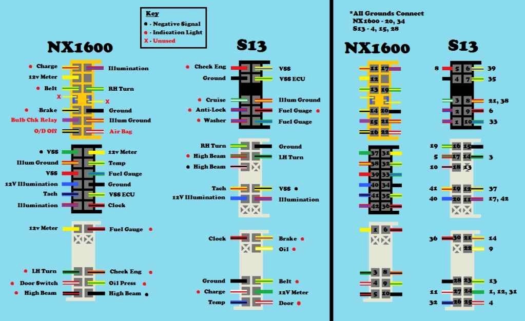
S13 Ecu Wiring Diagram. S13 Ecu Wiring Diagram. I just got my KA24E swap back to my house and noticed that the Just saw this I should have a wiring diagram for this if you still need it. RB26DETT ECU PINOUT. Toyota 1kz Ecu Pinout 2 Ecu Car Ecu Toyota from www.pinterest.com. S14 SR20DET Zenki ECU PINOUT. 15 rows 1988 - 1991 Nissan Silvia S13 ... Jun 16, 2013 · S13 69-71 Suspension H.D. with Sway Bar S15 69-71 Hemi Suspension with Sway Bar S16 71 only Suspension H.D. Police S17 69-70 Reduced Rate Suspension S21 71 only Shocks H.D. 1"-Front / Monroe Load Levers Rear S22 71 only Shocks H.D. Monroe Front / Load Levers Rear S25 69-71 Firm Ride Shocks 1" Front & Rear S28 69-71 Firm Ride Shocks 1" … Select Your Chassis for Wiring Instructions. Nissan 240sx S13 USDM LHD. Nissan 240sx S14 USDM LHD. Nissan Silvia & 180sx JDM RHD. Nissan 200sx S13 EURO LHD. Nissan Silvia S14 JDM RHD. BMW E36. Classic Datsun 510, Z/ZX, etc. Universal / Standalone. S13 wiring diagr

40 2000 toyota camry fuse box diagram

Image
This article applies to the Toyota Camry (1997-2011). You can find out if a fuse needs to be replaced by looking at the fuse box panel and the owner's manual. Keep reading to learn about replacing blown fuses. Figure 1. This diagram identifies the general position of the fuse box panel in a Camry. Replacing Broken Fuses See more on our website: https://fuse-box.info/toyota/toyota-camry-xv20-1997-2001-fusesFuse box diagrams (location and assignment of electrical fuses) Toyota... 2000 toyota 4runner fuse box diagram power to every thing but engine will not turn over - Cars & Trucks question. Search Fixya. Browse Categories Answer Questions ... Toyota Camry (1999 - 2000) - fuse box diagram - Auto Genius www.autogenius.info > toyota-camry-1999-2000-fuse-... 2000 toyota camry fuse box diagram

40 recurve bow diagram

Image
Slide the string's large loop over the bow's upper limb, positioning the string on the correct side of the bow. Fit the smaller loop into the notch on the lower limb, double-checking that it fits snugly. Since the bow is in a relaxed position, the string should have plenty of slack. The lower limb is on the heavier side of the handle. the arrow's left/right position on the bow, it is necessary to find and mark the exact center of the limbs on a recurve bow, or what is termed the Òbalanced limb centerÓ on a compound bow. Recurve Bows To find the limb center for recurve bows, place a piece of masking tape across the inside of each limb a few inches from the riser. Recurve Bow Diagram (Pattern) WT: 0.0 Size: TINY Class: ALL Race: ALL Stackable up to 200 EQ item ID: 45175 Recurve bow diagram

39 venn diagram of renewable and nonrenewable resources

Image
Following are examples of non-renewable resources: Minerals, Animals, Plants, Fossil fuels (petroleum) Coal Natural gases Nuclear energy Renewable and non-renewable energy resources venn diagram Venn diagram What are fossil fuels and how are they formed? Dec 20, 2021 - This worksheet requires students to compare and contrast renewable and non-renewable energy resources. To complete the activity, students must cut and paste words and phrases into a Venn diagram. An answer key is included. View Renewable v. Nonrenewable Resource Venn Diagram from SCIENCE IBSL at Southwest High School. Name_ Date_ Primary Venn Diagram Organizer Concept/subject: Renewable vs. Nonrenewable Resources Item Venn diagram of renewable and nonrenewable resources