43 diagram of electric motor
Baldor Motor Wiring Diagram - baldor 5hp motor wiring diagram, baldor brake motor wiring diagram, baldor dc motor wiring diagram, Every electrical structure is composed of various diverse parts. Each component should be set and connected with different parts in particular way. If not, the arrangement will not function as it should be. Electric Motor Wiring Diagram from www.electricmotorwarehouse.com Print the wiring diagram off plus use highlighters to trace the signal. When you make use of your finger or perhaps the actual circuit with your eyes, it is easy to mistrace the circuit. 1 trick that We 2 to printing a similar wiring plan off twice.
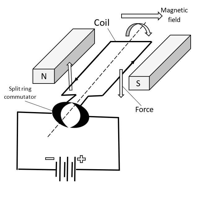
(a) An electric motor converts mechanical energy into electrical energy. View Answer NCERT Question 11 - Draw a labelled diagram of an electric motor. Explain its principle and working. What is the function of a split ring in an electric motor? View Answer NCERT Question 12 - Name some devices in which electric motors are used. View Answer

Diagram of electric motor
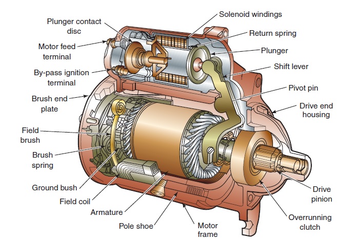
Armature Coil: It helps the motor to run. Brushes: It is a device that conducts current between stationary wires and moving parts, most commonly the rotating shaft. What Is The Working Principle of An Electric Motor? The working of an electric motor is based on the fact that a current carrying conductor produces a magnetic field around it. Single Phase Motor Wiring Diagram With Capacitor - baldor single phase motor wiring diagram with capacitor, single phase fan motor wiring diagram with capacitor, single phase motor connection diagram with capacitor, Every electrical arrangement is made up of various unique pieces. Each component ought to be placed and linked to different parts in particular manner. Circuit diagram of motor inching control (2) The so-called inching control refers to:Press the button, the motor will be powered on to run; release the button, the motor will lose power and stop running. This control method is often used in the control of the electric hoist's lifting motor and the motor control of the lathe carriage moving ...
Diagram of electric motor. Dayton Electric Motor Wiring Diagram - Wiring Library - Dayton Electric Motors Wiring Diagram Download. You are able to usually rely on Wiring Diagram being an essential reference that may assist you to conserve time and money. With the aid of the book, you can easily do your own personal wiring assignments. Century electric motor wiring diagram. Bikes that assist the riders pedal-power ie. Polaris Booster Pump 34 HP Motor - B625 It is recommended that the motor shaft seal and backplate o-ring be replaced concurrent with the new motor. 6 Full PDFs related to this paper. A short summary of this paper. The Complete Guide to Electrical Wiring. Jan 16, 2019 - Find Cash Advance, Debt Consolidation and more at 24Inchhairextensions.net. Get the best of Insurance or Free Credit Report, browse our section on Cell Phones or learn about Life Insurance. 24Inchhairextensions.net is the site for Cash Advance. After the motor has had time to speed up, another set of "starter" contacts bypass line power around the resistors, directly to the motor windings. Draw a diagram showing how this could be done for a single-phase electric motor, using two starter contacts: "R" for "run" and "S" for "start".
Q. 11. Draw a labelled diagram of an electric motor. Explain its principle and working. What is the function of a split ring in an electric motor? Electric Motor & Wiring DiagramAmazon Printed Bookshttps://www.createspace.com/3623928Amazon Kindle Editionhttp://www.amazon.com/Automotive-Electronic-Diagno... Marathon Electric Motor 1 Hp Wiring Diagram | Wiring Diagram – Marathon Electric Motor Wiring Diagram. Wiring Diagram will come with a number of easy to stick to Wiring Diagram Instructions. It’s supposed to help all the average consumer in creating a proper program. These guidelines will probably be easy to grasp and use. Circuit diagrams communicate information quickly and efficiently. ... It is the power circuit that passes electric-ity to the motor enabling it to run. For this reason, it is some-times referred to as the motor circuit. Common Control — power and control circuits at same volt-
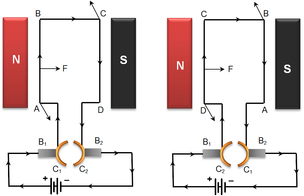
Current in the length PQ flows from P to Q and the magnetic field acts from left to right, normal to length PQ. Therefore, according to Fleming's left hand rule ... In this video I'm going to draw labelled diagram of electric motor for construction of an electric motor.Construction of Electric Motor ... Draw a neat diagram and label it. Electric motor. ... Construction: Electric motor consists of the following parts: Rectangular coil: A large number of ... A blower motor is part of the heating and cooling system in a house or other building. It pushes heated or cooled air through the ductwork of the building. Blower motors are also used in automotive heating and cooling systems to move heated...
Click here👆to get an answer to your question ✍️ Draw a labelled diagram of an electric motor. Explain its principle and working. What is the function of a split ring in an electric motor?
To 480 VAC 120 VAC Toggle switch M1 M1 Motor L1 L2 Next the schematic diagram. 18 Ge 1 2 Hp Electric Motor Wiring Diagram Wiring Diagram Wiringg Net Electric Motor Electrical Circuit Diagram Electricity . You can use a schematic to actually. Motor schematic diagram. Also explain the operation of this motor control circuit.
How To Draw Electric Motor || Diagram For Class 10th || Electric Motor ... Class 10 easy diagram, Electric Motor Diagram, pencil drawing, ...
Marathon Electric Motor Wiring Diagram – 5 hp marathon electric motor wiring diagram, marathon 2 hp electric motor wiring diagram, marathon electric ac motor wiring diagram, Every electrical arrangement is made up of various unique pieces. Each component ought to be placed and linked to other parts in particular way. Otherwise, the structure will not work as it should be.
Feb 11, 2020 - Electrical - AC & DC - Bodine Electric Motor Wiring - I purchased a Bodine electric motor from a surplus store, but there is no wiring diagram on it. Perhaps someone can help. Here are the details:
We supply electrical energy to an electric motor. An efficient motor transfers most of this energy as kinetic energy (useful work). Only a small fraction is wasted as it heats up the surroundings. We can show this in a Sankey diagram (Figure 12). The size of the arrows represents the amount ...
May 4, 2020 - Draw a labelled diagram of an electric motor. Explain its principle and working. What is the function of a split ring in an electric motor?AnswerElectric Motor looks likePrinciple of an electric motorAn electric motor works on the principle thatwhen a rectangular coil is placed in a magnetic field a
Electrical Formulas103-104 List of Tables Table 1 Standard Elementary Diagram Symbols 1 Table 2 NEMA and IEC Terminal Markings 4 Table 3 NEMA and IEC Controller Markings and Elementary Diagrams 4 Table 4 Control and Power Connections for Across-the-Line Starters, 600 V or less4 Table 5 Motor Lead Connections 64
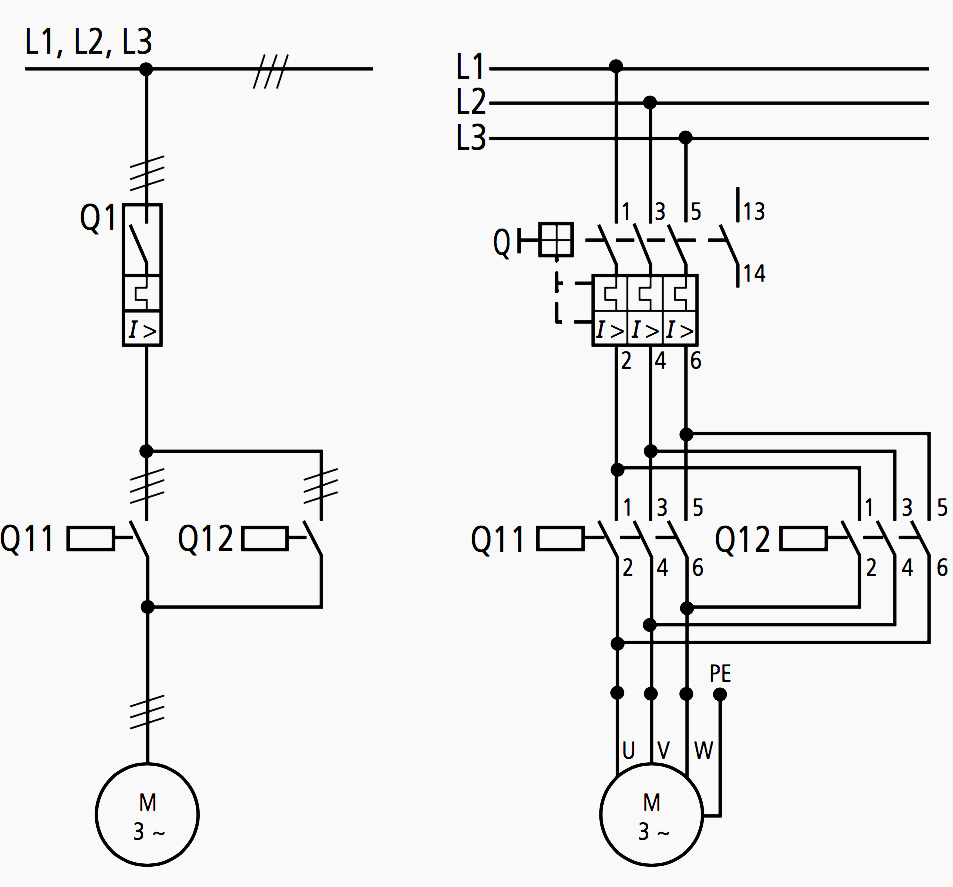
March 25, 2018 - Home / Download Center / Electrical Engineering Books and Technical Guides / Industrial automation and control guides / All about wiring of electric motors ... Diagrams indicate the voltage-free or current-free status of the electrical installation. A distinction is drawn between:
In this video, Jamie shows you how to read a wiring diagram and the basics of hooking up an electric air compressor motor. These tips can be used on most ele...
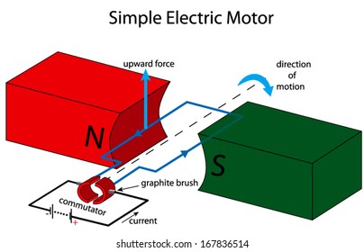
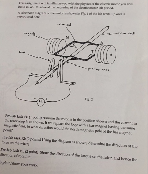
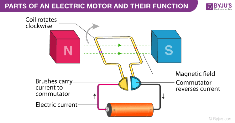
Working of electric motor: As shown in the diagram, when a current is passed through the coil PQRS the coil starts rotating anti clockwise because a downward force acts on length PQ and at the same time an upward force acts on RS. Therefore, the coil rotates in anti clockwise direction.
December 17, 2021 - Answer: I have compiled a group of single phase internal electric motor diagrams and terminal connections below. At the bottom of this post is also a video about DC shunt motors. NOTE: Some text links below go to applicable products on Amazon and Ebay. As an Amazon Associate I earn from qualifying ...
As 183 wiring diagram with switch. Ac motor diagrams basic stator and rotor operation an ac motor converts electric energy into mechanical energy. Always refer to your thermostat or equipment installation guides to verify proper wiring. Wondering how a capacitor can be used to start a single phase motor.
Basic AC Motor Operation. An AC motor has two basic electrical parts: a "stator" and a "rotor" as shown in Figure 8. The stator is in the stationary electrical component. It consists of a group of individual electro-magnets arranged in such a way that they form a hollow cylinder, with one pole of each magnet facing toward the center of the group.
Fantech is a leading provider of fans and air ventilation technologies. Designers and manufacturers of fans such as exhaust fans & ventilation fans, ventilation equipment, sound control products and related equipment for the ventilation and air conditioning industry.
Motor connection diagram for a 4 wire reversible P.S.C. Schematic shows CW rotation facing the drive end. L1 and l2 are designated as the two connection points representing the two electricity flow path inherent with single phase circuits where a single phase supply voltage is fed to the motors internal circuit.
Find Electric motor diagram stock images in HD and millions of other royalty-free stock photos, illustrations and vectors in the Shutterstock collection. Thousands of new, high-quality pictures added every day.
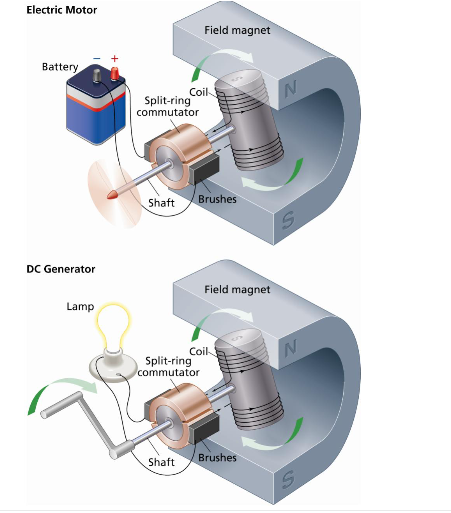
October 25, 2021 - Artwork: A simplified diagram of the parts in an electric motor. Animation: How it works in practice. Note how the commutator reverses the current each time the coil turns halfway. This means the force on each side of the coil is always pushing in the same direction, which keeps the coil rotating ...
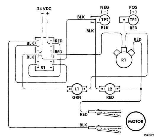
Electric Motor Controls, G. Rockis, 2001 Wiring Diagrams Wiring (connection) diagram - a diagram that shows the connection of an installation or its component devices or parts. Wiring diagrams show, as closely as possible, the actual location of each component in a circuit, including the control circuit and the power circuit. 4
Learn about and revise electromagnetism, the motor effect and its applications in motors with GCSE Bitesize Combined Science.
3 phase motor starter wiring diagram pdf source. It shows the parts of the circuit as simplified shapes and also the power and also signal links in between the tools. 3 Wire Submersible Well Wiring Diagram Get Free Circuit Diagram Electrical Circuit Diagram Capacitors The first step is to figure out the voltage of your …
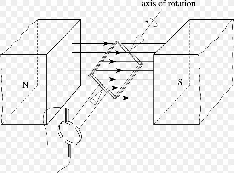
Draw a labelled diagram of an electric motor. Explain its principle and working. ... An electric motor is a rotating device that converts electrical energy to mechanical energy. Principle involved : It is based on the fact that a current-carrying coil experiences equal and opposite forces on its edges which rotates it continuously.
Q = 2π x (Stored Energy/ Power loss) In a Resonator, Q is the ratio between stored energy in resonator and energy supplied by generator to keep signal amplitude constant Q = 2π (Maximum Energy Stored/Energy dissipate per Cycle) in the coil. Good to Know *1:
Principle: An electric motor (dc motor) works on the principle that when an electric current is passed through a conductor placed normally in a magnetic field, ...
The electric motor operation is based on the following points: • At least one of the two magnetic field is generated by a solenoid carrying a current. • Phase relation between the rotor and stator magnetic field (i.e. the load angle) must be always greater than 0° in order to keep the motor in motion (negative angles reverse the
Motor Connection Diagrams. Motor Connection Diagrams. Electric Motor Wire Marking & Connections. For specific Leeson Motor Connections go to their website and input the Leeson catalog # in the "review" box, you will find connection data, dimensions, name plate data, ...
electric fan motor wiring diagram pdf. GALGO PRE-Q Tread Uncategorized electric fan motor wiring diagram pdf. January 28, 2022 / By / best hotels in ixtapa-zihuatanejo / christmas attic window quilt pattern.
Cars and other products with electric motors are becoming increasingly popular, and that’s not necessarily a bad thing. They offer drivers plenty of advantages compared to traditional engines, ranging from saving money to requiring minimal ...
always use wiring diagram supplied on motor nameplate. w2 cj2 ui vi wi w2 cj2 ui vi wi a cow voltage y high voltage z t4 til t12 10 til t4 t5 ali l2 t12 ti-blu t2-wht t3.org t4-yel t5-blk t6-gry t7-pnk t8-red t9-brk red tio-curry tii-grn t12-vlt z t4 til t12 tio til
An electric motor is an electrical machine that converts electrical energy into mechanical energy. Most electric motors operate through the interaction between the motor's magnetic field and electric current in a wire winding to generate force in the form of torque applied on the motor's shaft.
Browse 37 electric motor diagram stock photos and images available, or start a new search to explore more stock photos and images. The enlarged bottom bracket area which houses the motor of the e-bike belonging to Russell Polsgrove is pictured at the Blue Hills Reservation in...
While motorized scooters can be quite useful for people with disabilities as well as older people, they can also be expensive. Luckily, as with cars, you can save money by choosing to buy a used one. Just like any other vehicle you can buy ...
A client has two motors which he wants to run them in two modes I, Manual mode Ii, Automatic mode. On the manual mode, motor A and motor B can be controlled separately by selector switch. On the automatic mode, motor A has to run for 3 minute then motor B comes on also. Can you help me with the controlled diagram
The "flipping the electric field" part of an electric motor is accomplished by two parts: the commutator and the brushes. Advertisement The diagram shows how the commutator (in green) and brushes (in red) work together to let current flow to the electromagnet, and also to flip the direction that the electrons are flowing at just the right moment.
Literally a circuit is the course that enables electrical. Baldor motor capacitor wiring diagram a novice s overview of circuit diagrams. Baldor Fdl3514m 1 5hp 1ph 115 230v Tefc Farm Duty Electric Motor In 2020 Electric Motor Electricity Industrial Electric It reveals the parts of the circuit as streamlined shapes and the power and signal …
Draw a labeled diagram of an electric motor. Explain its principle and working. What is the function of a split ring in an electric motor?
General Electric Motor Wiring Diagram from www.doityourself.com Print the wiring diagram off plus use highlighters to trace the signal. When you make use of your finger or perhaps the actual circuit with your eyes, it is easy to mistrace the circuit. 1 trick that We 2 to printing a similar wiring plan off twice.
Any advice given in this website is only general and every single application must be handled as a specific case. Any connections made to an electric motor should be carried out by qualified persons. The three stator windings are connected in star (Y) or delta (∆).
Source: trumpgrets.club. Size: 109.56 KB. Dimension: 800 x 563. DOWNLOAD. Wiring Diagram Sheets Detail: Name: single phase marathon motor wiring diagram – Single Baldor Motor Wiring Marathon Electric Motor Wiring Diagram 5a In Baldor Motors 939×1024. File Type: JPG.
Circuit diagram of motor inching control (2) The so-called inching control refers to:Press the button, the motor will be powered on to run; release the button, the motor will lose power and stop running. This control method is often used in the control of the electric hoist's lifting motor and the motor control of the lathe carriage moving ...
Single Phase Motor Wiring Diagram With Capacitor - baldor single phase motor wiring diagram with capacitor, single phase fan motor wiring diagram with capacitor, single phase motor connection diagram with capacitor, Every electrical arrangement is made up of various unique pieces. Each component ought to be placed and linked to different parts in particular manner.
Armature Coil: It helps the motor to run. Brushes: It is a device that conducts current between stationary wires and moving parts, most commonly the rotating shaft. What Is The Working Principle of An Electric Motor? The working of an electric motor is based on the fact that a current carrying conductor produces a magnetic field around it.















Comments
Post a Comment