43 transmission line diagram
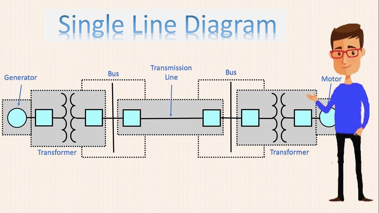
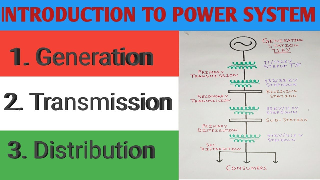
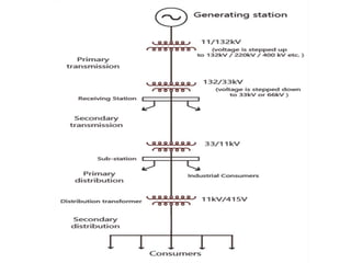
Nov 13, 2015 · A typical layout of a generating, transmission and distribution network of a large system would be made up of elements as shown by a single-line diagram of Figure 1 although it has to be realized that one or more of these elements may be missing in any particular system. For example, in a certain system, there may be no secondary transmission and in another case, when the generating station is nearby, there may be no transmission and the distribution system proper may begin at the generator ... Single Line Diagram: In single line representation of power system, the components of the system are represented by standard symbols & the transmission lines are represented by straight lines. ³Hence a single line diagram is diagrammatic of power system in which the components are
Dec 03, 2018 · What is a Single Line Diagram? A Single Line Diagram or a One Line Diagram is a simple way to draw the Electrical Circuit in a Power System. By adopting this Electrical Line Diagram the Complexity of the Pictorial Representation can be reduced. A typical Electrical Single Line Diagram Consist of a. Generator (Generating Station) Step Up Transformer

Transmission line diagram
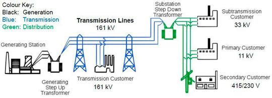
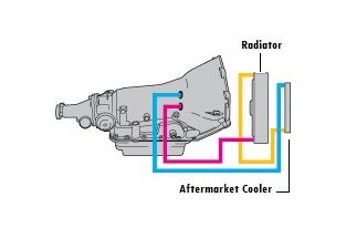
Single line diagram of AC power transmission system A typical single line diagram that represents the flow of energy in a given power system is shown below: Electric power is commonly (or usually) generated at 11 kV in generating stations in India and Europe. While in some cases, generation voltage might be higher or lower. A set of commonly-used single-line diagram symbols appears on the next two pages. An example of a single-line diagram showing multiple generating stations, substations, transmission lines, and distribution lines appears here. Note the coloring used to illustrate circuit breaker states (green = off and red = on) which is how single-line diagrams ... The transmission cooling line system is vital to any automatic transmission. It circulates the hot fluid away to the radiator via cooler lines and returns the cooled fluid back to the transmission. A loss of fluid leading to an overheated transmission can be devastating as the system loses its ability to cool. Optimal transmission temp is about ...
Transmission line diagram. •Transmission plans are often evaluated in forward looking ten year plans, and are refined as circumstances change. It typically takes longer to develop, permit and construct a transmission line than it does to develop a generation facility. •FERC has required that transmission planning processes be open, and transparent, and that Sponsored Download Links mack t2070 transmission diagram mack truck air line manual free PDF ebook downloads Manual transmission & automatic - Choose our automatic transmission or automated manual transmission. Our automated manual transmission offers a powerful ride while enhancing fuel economy. The below transmission cooler installation diagram shows the transmission fluid flow direction and how the fluid will be routed through a new external cooler. You will need to determine which line is the return for the transmission. You want the already warm fluid to flow into the external cooler to help better control fluid temperatures, so ... A short transmission line is defined as a transmission line with an effective length less than 80 km (50 miles), or with a voltage less than 69 kV. Unlike medium transmission lines and long transmission lines, the line charging current is negligible, and hence the shunt capacitance can be ignored. For short length, the shunt capacitance of this ...
700r4 Transmission Line Routing. R4 trans line routing Transmission & Drive line. I have a stock style radiator for an automatic and a R4. The lower radiator line should be routed to the external cooler or back to the. MONSTER'S Website: schematron.org Give us a call at: Curt shows the coolant lines on a R4 and explains the process. Order Ford F250 Super Duty Transmission Cooler Line Assembly online today. Free Same Day Store Pickup. Check out free battery charging and engine diagnostic testing while you are in store. 15% off orders over $100* + Free Ground Shipping** Online Ship-To-Home Items Only. Use Code: DEALS4JAN In electrical engineering, a transmission line is a specialized cable or other structure designed to conduct electromagnetic waves in a contained manner. The term applies when the conductors are long enough that the wave nature of the transmission must be taken into account. This applies especially to radio-frequency engineering because the short wavelengths mean that wave phenomena arise over ... 1999 2007 Gm Trucks Transmission Oil Cooler Hose New Oem 15809053. Chevrolet Venture Transmission Diagram Troubleshooting Circuits. How To Determine Which Line Is The Return For Installing. 15005718 4l80e 4l85e Trans Cooler Lines Workhorse Parts. 2006 Chevrolet Colorado Fuse Box Diagram Image Wiring.
Shop for New Auto Parts at 1AAuto.com http://1aau.to/c/182/f/transmission-oil-coolersTransmission cooling lines deliver and return transmission fluid between... 2- For a 50 ohm lossless transmission line terminated in a load impedance ZL=100 + j50 ohm, determine the fraction of the average incident power reflected by the load. Also, what is the magnitude of the average reflected power if |Vo|=1? 3- Make sure you understand the slotted line problem. Sep 28, 2018 · Figure 9: Circuit model of a lossless transmission line Under dc conditions (steady-state when driven by a dc source) inductors act as short circuits and capacitors act as open circuits. Thus in steady state the circuit in Figure 1 is equivalent to the circuit in Figure 10 where the transmission line is modeled as an ideal conductor. The concept of the bounce diagram is useful to find a step response on a terminated lossless line: 2. v t. g ( ) ( ) ( ) v t Vut. g = 0. V. 0. t. Generator voltage. vt. g ( ) Z. 0 +-z =0. V. 0 [V] t =0. R. L. zL = R. g. Lossless line. Note: The bounce diagram is useful if the source is a step function or a rectangular pulse (discussed later in these notes). If the source is something else, it is
Basics of Electrical Power Transmission System ...
Hi, I am trying to plot the dispersion diagram for a transmission line metamaterial IFA antenna, consisting of a capacitor in series and an inductor in parallel to the antenna. As far as I know, the dispersion diagram is the plot of frequency vs. phase of S21, as phase (theta) is beta*length...

Performance of Transmission Line | Electrical4U
The figure below represents the equivalent circuit diagram of a transmission line: Here, the two conducting wires have a certain length and the parameters of the transmission line is distributed over all its length. These parameters are R, L, C and G which we will discuss in detail in the upcoming section. The two conducting wires due to ...
single line diagram of power system | One line diagram | power line diagram
transmission line, the greater the inductance of the line. – Since the phases of a high-voltage overhead transmission line must be spaced further apart to ensure proper insulation, a high-voltage line will have a higher inductance than a low-voltage line. – Since the spacing between lines in buried cables is very small, series
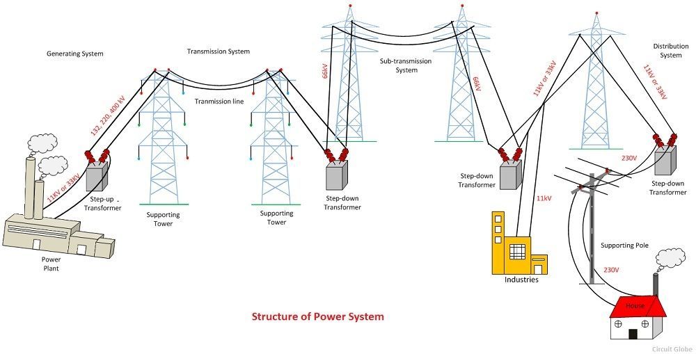
What is Power System? Definition & Structure of Power System ...
This 4l60e transmission cooler lines diagram provides an easy to follow example of how your 4l60e's cooling path works. 4l60e Cooler Line Flow Direction. The 4l60e transmission cooler line flow is very easy to follow. As the gif above shows, the bottom line is the hot line which sends warm transmission fluid out to the factory trans cooler ...

Transmission System: Concept of Energy Distribution
Click here to see Chevy Silverado Transmission Oil Cooler Line Repair - DIY https://youtu.be/BYaK2oQWu6g Just a short video showing how I repaired the leakin...

File:Transmission line schematic.svg - Wikimedia Commons
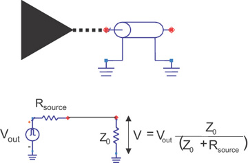
Transmission Line Theory Dr. M.A.Motawea Introduction: In an electronic system, the delivery of power requires the connection of two wires between the source and the load. At low frequencies, power is considered to be delivered to the load through the wire. In the microwave frequency region, power is considered to be in electric ...
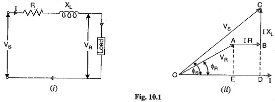
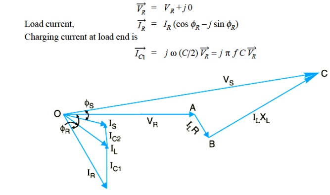
Performance of Single Phase Short Transmission Line Voltage
A transmission line is a wire with a uniform goemetry along its length: the capacitance and inductance of any segment is proportional to its length. We represent as a large number of small inductors and capacitors spaced along the line. The signal speed along a transmisison line is predictable.
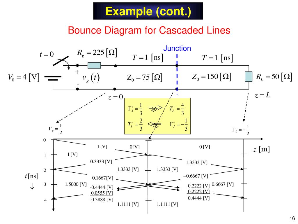
Notes 8 Transmission Lines (Bounce Diagram) - ppt download
Home > Tech Info > Trans Cooler Return Line Chart. Trans Cooler Return Line Chart Transmission Location Chrysler / AMC 404, 413, 470 : Top: 41TE, 41AE, (604) ... I promise you that the next transmission I have to replace or any other person I hear of needing a transmission I will be heavily promoting Monster Transmission and tell them that I ...
ECE 353 DIGITAL MICROELECTRONICS
Bewley's lattice diagram offers the advantage of describing the results for attenuation and wave distortion without any difficulty. This technique is efficient for the lossless or distortionless line. Good accuracy can be achieved by lumping resistance at one or more points along the line. The history of any wave can be determined easily.
Power System Single Line Diagram | Power Generation Transmission Distribution.
We provide detailed Transmission and Transfer Case Assembly Diagrams for both manual transmissions and transfer cases. These free illustrations can assist you in identification of the correct parts that you may need, you can also use these illustrations to assist you with proper re-assembly of your unit.. If you don't see the Transmission and Transfer Case Assembly Diagrams & Parts ...

Transmission Line Reflections: Bounce Diagram - In Compliance ...
Line Going to the Transmission Case: Lineartronic CVT Lower line: TOYOTA: Transmission: Location FWD: All (Except Tercel A55 & A55F) Bottom Tercel A55 & A55F: Rear U140 Series: Bottom U150/250 Series: Bottom U240 Series: Bottom U340 Series: Bottom U660: Top 46DE/DF: Rear A340: Rear A750: Top Most: Rear AA80E: Front: ZF: Transmission Location ...

HVDC - High Voltage Direct Current Power Transmission
The transmission cooling line system is vital to any automatic transmission. It circulates the hot fluid away to the radiator via cooler lines and returns the cooled fluid back to the transmission. A loss of fluid leading to an overheated transmission can be devastating as the system loses its ability to cool. Optimal transmission temp is about ...
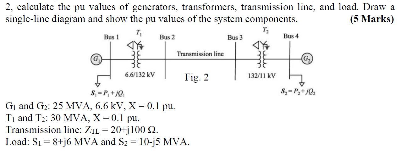
Solved 2, calculate the pu values of generators, | Chegg.com
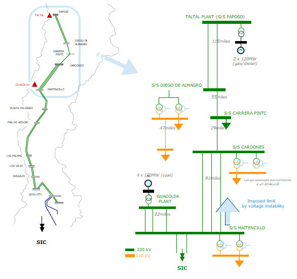
A set of commonly-used single-line diagram symbols appears on the next two pages. An example of a single-line diagram showing multiple generating stations, substations, transmission lines, and distribution lines appears here. Note the coloring used to illustrate circuit breaker states (green = off and red = on) which is how single-line diagrams ...

Ideal Transmission Line Fundamentals
Single line diagram of AC power transmission system A typical single line diagram that represents the flow of energy in a given power system is shown below: Electric power is commonly (or usually) generated at 11 kV in generating stations in India and Europe. While in some cases, generation voltage might be higher or lower.
Sustainability | Free Full-Text | Issues and Challenges in ...

Short Transmission Line (Phasor Diagram & Performance ...
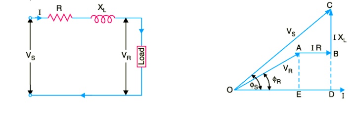
Performance of Single Phase Short Transmission Lines
Basics of an electrical power transmission system
Transmission Line Monitoring System Using Internet Of Things

HVDC Transmission
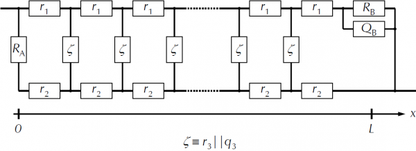
Use of Transmission Lines Electrochemical Impedance Spectroscopy

Basics of Electrical Power Transmission System ...
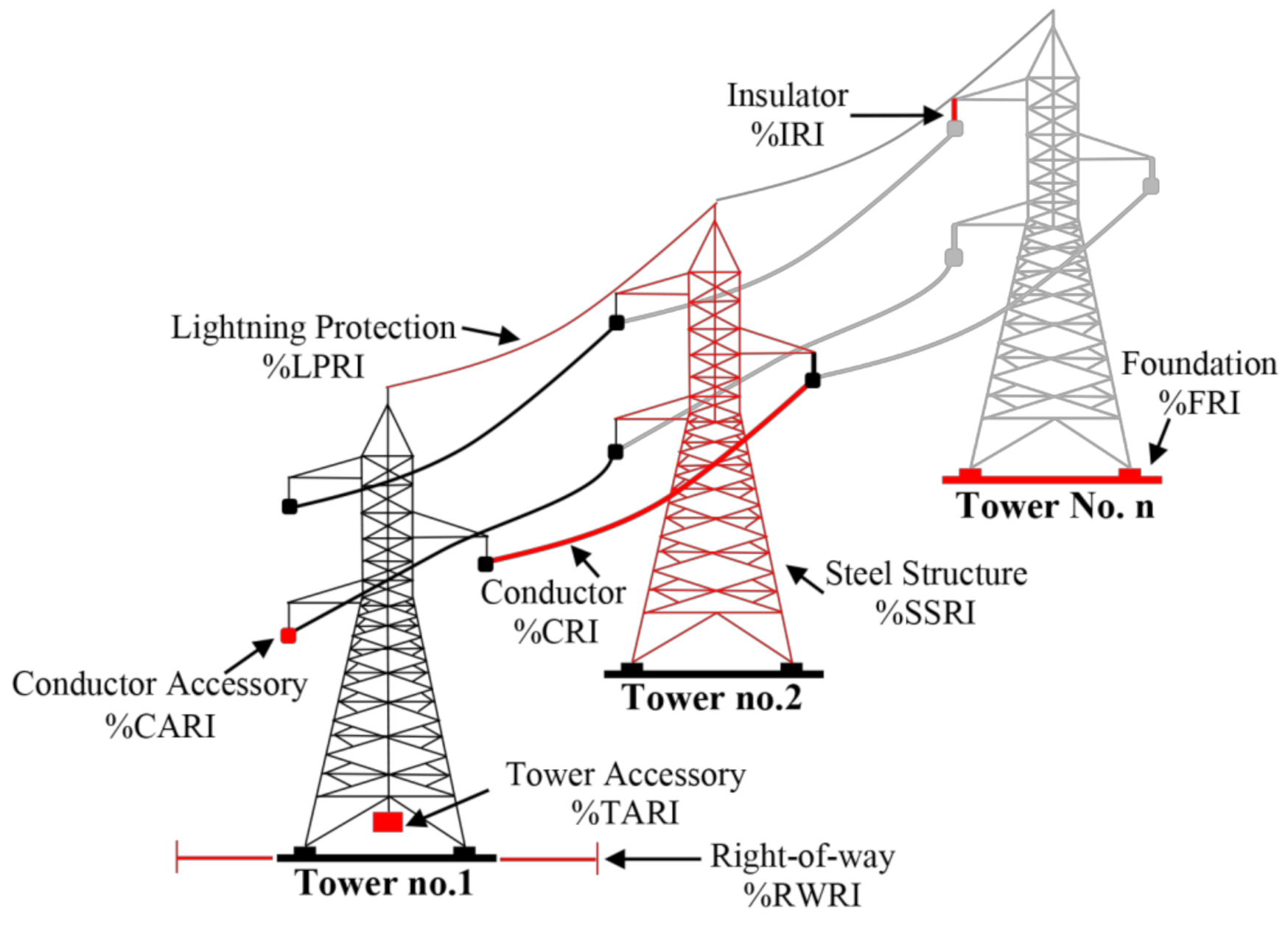
Sustainability | Free Full-Text | D-distance Risk Factor for ...

A Field Guide To Transmission Lines | Hackaday
7.12 Driving a Transmission Line | The Physical Basis of ...

Short Transmission Line (Phasor Diagram & Performance ...

Electrical Transmission and Distribution System - An ...

Ferranti Effect in Transmission Lines

Single Line Diagram of Transmission Distribution
TDU - Unit 01 Transmission system
Increase of power transmission | Estudios Eléctricos
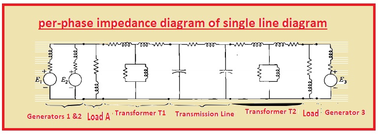
Impedance and Reactance Diagrams Of Electrical System - The ...

05 - Phasor Diagram of Short transmission line || Power system analysis || Bangla

Overhead power line Drawing Pylon Electricity Diagram ...

Transmission Line Theory - an overview | ScienceDirect Topics
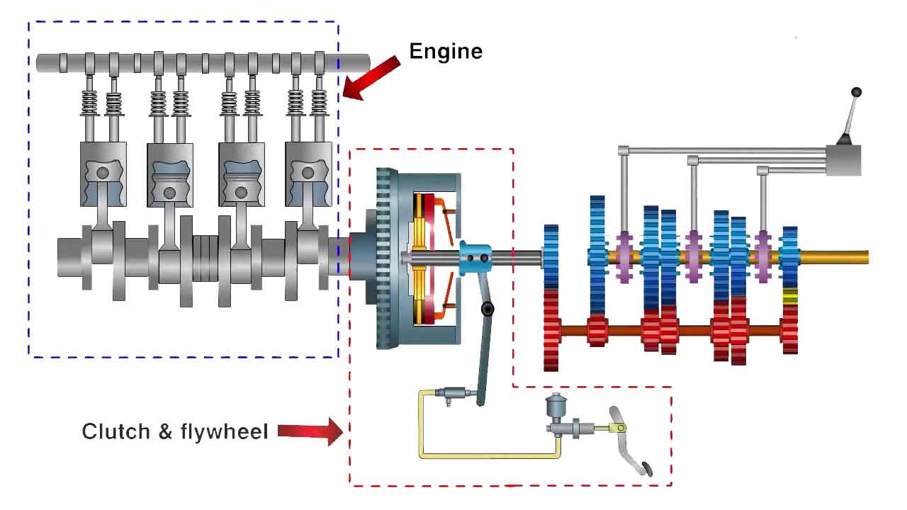
Automobile Transmission System and its Components
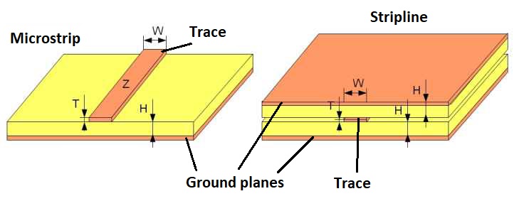
Routing guidelines for RF PCBs

Power Station: Power Transmission

The main threats in transmission lines and their impact ...

Transmission Lines: Parameters, Types & Theory | Electrical4U
Medium Transmission Lines
4l60e Transmission Cooler Line Diagram & Flow Direction ...

Use pairs of transformers to increase transmission line ...


Comments
Post a Comment