39 multi battery isolator wiring diagram
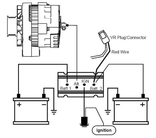
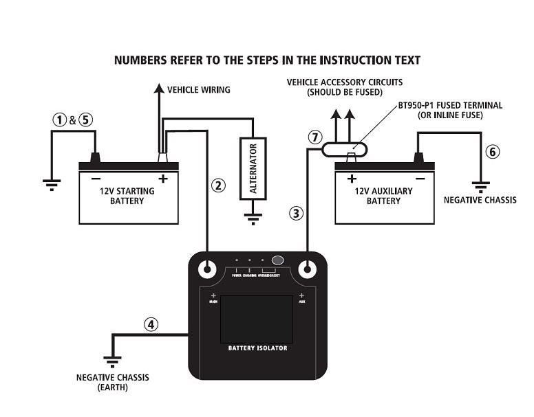
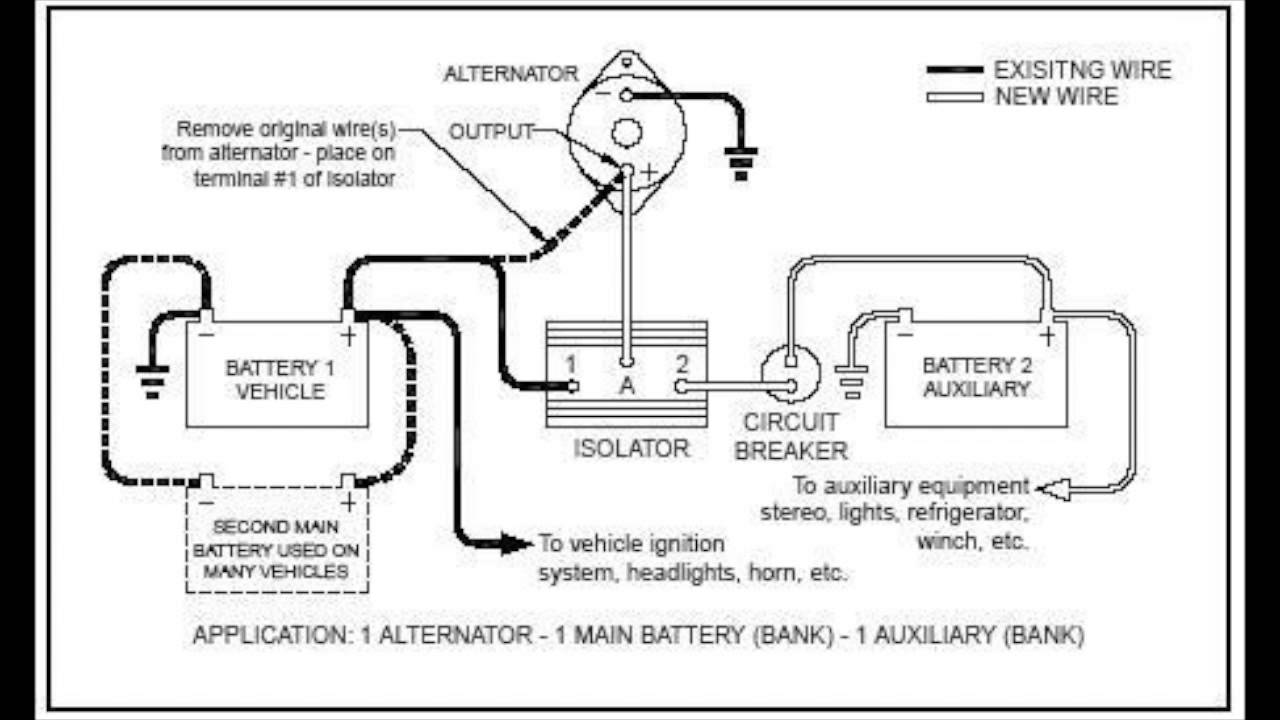
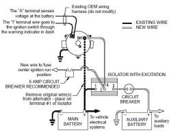
Sure Power 9523a Wiring Diagram - schematron.org (Looking at the wiring diagrams for both the 60 and 62's shows the external wiring is the same.) I spoke to Sure Power's. Multi-Battery Isolators Sure Power Multi-Battery Isolators. First, make sure you have all the tools, wire, connectors and circuit breakers you will need. Sure Power offers a range of installation wiring kits which make the ... PDF INSTALLATION INSTRUCTIONS - Northern Tool battery 6. Mount a circuit breaker as near to the auxiliary battery as practical, and away from engine or exhaust heat (see application chart for proper size). Connect one end of a new wire ensuring it is the correct size to the "2" terminal of the Isolator. Run the wire to the circuit breaker and connect it to the "AUX" terminal.
Multi Battery Isolator Wiring Diagram - schematron.org The installation of a Sure Power multi-battery isolator is quite simple as long as you carefully read and . in diagram, being careful not to over torque the. Wiring Diagram for Deka amp Battery Isolator # DW the truck battery from excessive discharge and to regulate current in a multi-battery system.The Battery Isolator Module is part of the ...

Multi battery isolator wiring diagram
betsson263-registrieren.de › 4-terminal-solenoid-diagram[email protected] - betsson263-registrieren.de email protected] Sure Power Battery Isolator Wiring Diagram - Wirings Diagram Sure Power Battery Isolator Wiring Diagram - sure power battery isolator wiring diagram, sure power battery separator 1314 wiring diagram, sure power battery separator wiring diagram, Every electrical structure is composed of various distinct parts. Each component ought to be placed and connected with other parts in specific manner. Otherwise, the structure will not work as it should be. Wiring a Battery Isolator - DoItYourself.com Then, cut a piece of the 14 gauge wire so that it fits between the alternators BAT terminal end and the end that is marked with an A on the battery isolator. Crimp on 2 electrical connectors that will attach BAT to A. Then use another piece of the wire to ground the negative cable of the car's battery to the frame.
Multi battery isolator wiring diagram. Multi battery Isolator. - Chevy and GMC Duramax Diesel Forum Gauges, Electronics and Wiring. Multi battery Isolator. Jump to Latest Follow Hey Everyone! Enter your ride HERE to be a part of this months Ride of the Month Challenge! 1 - 5 of 5 Posts. 4. 4500duramax · Registered. Joined Jan 24, 2011 · 5 Posts . Discussion Starter · #1 · Apr 12, 2011 ... How to Wire a Battery Isolator - HiFiSoundconnection How to Wire a Battery Isolator . Connecting multiple batteries can intimidate the do it your self installer, however the process is fairly simple when broken down. ... (a true 12 volt ignition wire can be found in the main power harness, under the steering column). ... Below is a diagram that shows the process. Dual Battery Boat Wiring Diagram - easywiring Dual battery isolator wiring diagram dual battery isolator circuit diagram dual battery isolator switch wiring diagram dual battery isolator wiring diagram every electric structure is made up of various unique pieces. I allows your house and start battery to remain isolated except for emergency conditions. Circuitry layouts are made up of two ... Miopro Battery Isolator Diagram - Great Installation Of ... sure power battery isolator wiring diagram - You will need an extensive, expert, and easy to comprehend Wiring Diagram. With this kind of an illustrative manual, you will have the ability to troubleshoot, stop, and complete your tasks without difficulty.
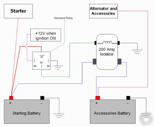
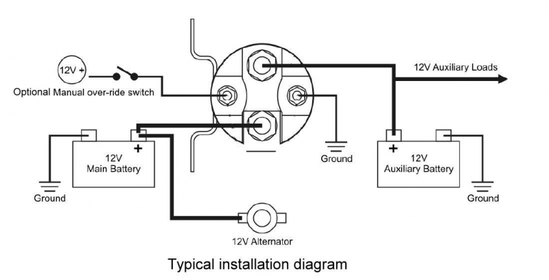
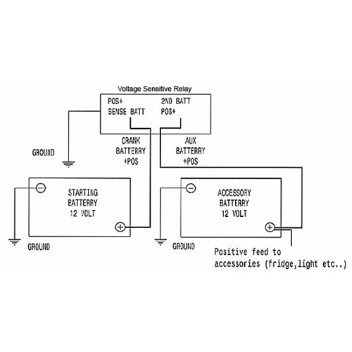
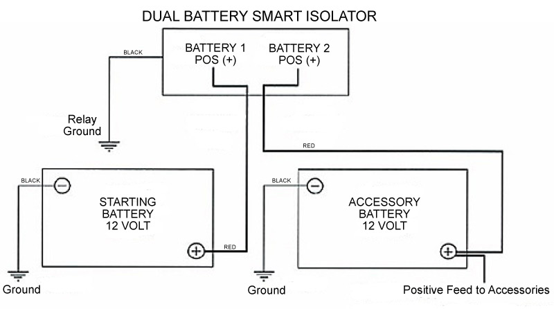
Dual Battery Isolator Schematic (simplified) Diagram Dual Battery Isolator Schematic. After answering numerous questions about different battery isolator schemes, I decided it would be easier to just build a webpage. Below you will find the basic design of 3 types of battery isolators with the pros and cons of each. Dual Battery Isolator Wiring Diagram - Wirings Diagram Dual Battery Isolator Wiring Diagram - dual battery isolator circuit diagram, dual battery isolator switch wiring diagram, dual battery isolator wiring diagram, Every electric structure is made up of various unique pieces. Each component should be placed and linked to other parts in particular way. Otherwise, the arrangement will not work as it should be. Rv Battery Isolator Wiring Diagram - Cadician's Blog Rv Battery Isolator Wiring Diagram. March 28, 2020. April 12, 2020. · Wiring Diagram. by Anna R. Higginbotham. rv battery isolator wiring diagram - You'll need an extensive, skilled, and easy to know Wiring Diagram. With this sort of an illustrative manual, you are going to be capable of troubleshoot, stop, and full your assignments with ease. Battery Isolator Wiring Diagram - easywiring Assortment of multi battery isolator wiring diagram. As stated earlier the lines at a sure power battery isolator wiring diagram signifies wires. As stated previous the traces in a dual battery isolator wiring diagram signifies wires. Then use another piece of the wire to ground the negative cable of the car s battery to the frame.
mowgli-adventures.com › camper-van-electrical-designCamper Van Electrical Design with Detailed Wiring Diagram Nov 05, 2021 · In the diagram above, I’ve indicated the output to the smart relay and the isolator from the leisure batteries, as explained a little earlier. The remainder of the diagram shows the set up of the output components. Cabling is run between the leisure batteries, fuses, switches and components as detailed above. Sure Power Battery Isolator Wiring Diagram - Wiring Diagram Sure Power Battery Isolator Wiring Diagram Luxury Sure Power Battery - Sure Power Battery Isolator Wiring Diagram. Wiring Diagram arrives with several easy to stick to Wiring Diagram Guidelines. It is intended to help all the average user in building a suitable program. These guidelines will probably be easy to grasp and implement. Noco Battery Isolator Wiring Diagram Wiring Diagram. The installation of a multi-battery isolator is quite simple as long as you carefully . Install hardware to the studs in the order shown in diagram, being careful not.The NOCO High-Performance Battery Isolator is a solid-state electrical device, which eliminates multiple battery drain and prolongs battery life. › question-60431How to Wire Two 6-Volt Batteries In Series to Double Output ... To wire two 6-volt batteries in series to produce 12-volts, you would connect the load to the positive terminal of battery # 1. Connect the negative terminal of battery # 1 to the positive terminal of battery # 2. Ground the negative terminal of battery # 2. I have produced a diagram showing the connections for you.

TrueAm UTV-SBI-CM UTV Dual Battery Connect & Monitor Kit ...
PDF Owners Manual & Installation Guide for ProMariner Battery ... Wiring: The battery cable should be sized in accordance with the engine manufactures recommendations. Ring terminal connectors sized in accordance with wire size (see table for wire sizes). 5/16" rings are recommended. Fuses must be used 7" from the alternator and 7" from the batteries on all leads coming from the battery isolator.

What is a battery isolator, diode, or solinoid? — Sun Power ...
Wiring diagram for Battery Isolator | etrailer.com Wiring diagram for Battery Isolator. Question: Not sure what post 1-2-A-and E go to. asked by: Mike. 1. Helpful Expert Reply: For your battery isolator similar to # DW08771, you will have connection posts for each battery and for an alternator. The main battery will connect to position one and the alternator to the A post.
Smart Battery Isolator-Dual Battery Wiring Diagram | Polaris ...
Wiring a Battery Isolator - DoItYourself.com Then, cut a piece of the 14 gauge wire so that it fits between the alternators BAT terminal end and the end that is marked with an A on the battery isolator. Crimp on 2 electrical connectors that will attach BAT to A. Then use another piece of the wire to ground the negative cable of the car's battery to the frame.
Ultimate Guide to the Best 12V DC Dual Battery Isolator in 2022
Sure Power Battery Isolator Wiring Diagram - Wirings Diagram Sure Power Battery Isolator Wiring Diagram - sure power battery isolator wiring diagram, sure power battery separator 1314 wiring diagram, sure power battery separator wiring diagram, Every electrical structure is composed of various distinct parts. Each component ought to be placed and connected with other parts in specific manner. Otherwise, the structure will not work as it should be.

Sure Power 12023A 120 Amp 2 Battery Isolator
betsson263-registrieren.de › 4-terminal-solenoid-diagram[email protected] - betsson263-registrieren.de email protected]
Battery Isolator Wiring Diagram?

Sure Power 95 Amp Multi-Battery Isolator | 1-Input, 2-Output
Dual Smart Battery Isolator 12V 140A Official Retailer ...
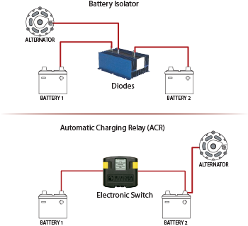
Battery Isolators and Automatic Charging Relays (ACRs): A ...
Battery Isolator Wiring

Dual Battery Isolator Schematic (simplified) Diagram

Wiring Guides – REDARC
Dual Battery Setups
Marine Battery Isolator – Blue Water Marine Service – West ...

battery isolator questions for a trailer | IH8MUD Forum
Battery Doctor Isolator 20090 and 20092 User Manual

Dual Battery Isolator Schematic (simplified) Diagram
500 Amp Heavy Duty Battery Isolator Solenoid & Relay
Silverado Dual Battery Kit Heavy Duty True® GM Chevy Sierra ...

Dual Battery Wiring | Dodge RamCharger Central
Battery isolator help! - TeamTalk

Battery Isolators - e RV
Canadian Energy™ - Battery Isolator : 101

Surepower Batery Isolator Installation Question | IH8MUD Forum

Battery Isolators - e RV

sterling power battery isolator - 70amp -3

How to install a Dual Battery set up with a isolator | Honda ...
Installing a Second Battery in a Boat
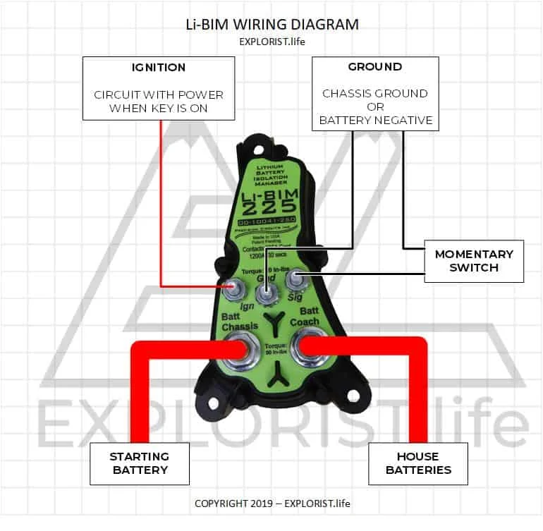
How to Wire an Li-BIM Lithium Battery Isolator – EXPLORIST.life

Installing the Dual Circuit Plus™ Battery Switch and CL ...
/auxiliarybatterywiringexample-5ae253713128340037cef3b0.jpg)
Is It Safe to Add an Auxiliary Battery?
True Dual Battery Smart Isolator 12v Relay for Auto/Boat/RV

How To Test A Battery Isolator - e Marine Systems

Lets talk dual battery isolators | Toyota FJ Cruiser Forum

Does Your Overland Rig need Dual Batteries? What You Need To ...

Dual Battery / Isolator / Accessory Wiring Diagram | Polaris ...

Battery Management Wiring Schematics for Typical Applications ...

POWERTECH MB3880 12V 140A Dual Battery Isolator Kit with ...
Wiring Diagram for Deka # DW08771 Battery Isolator | etrailer.com


Comments
Post a Comment