39 apm 2.8 wiring diagram
UCLA VA Physiatry Residency on Instagram: “Resident’s ... 12.09.2020 · 55 Likes, 13 Comments - UCLA VA Physiatry Residency (@uclava_pmrresidency) on Instagram: “Resident’s Corner: Name: David Huy Blumeyer, MD Year in residency: PGY-4 Where were you born…” Gallery of quadcopter wiring diagram guide diy quadcopter ... Quadcopter Wiring Diagram Guide Diy Quadcopter Diy images that posted in this website was uploaded by Feeds.canoncitydailyrecord.com. Quadcopter Wiring Diagram Guide Diy Quadcopter Diy equipped with a HD resolution 1377 x 2000.You can save Quadcopter Wiring Diagram Guide Diy Quadcopter Diy for free to your devices.. If you want to Save Quadcopter Wiring Diagram Guide Diy Quadcopter Diy with ...
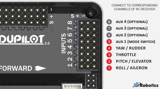
Archived:APM2.x Wiring QuickStart — Plane documentation Connect your APM's USB port to your computer and start Mission Planner and Select the "Connect" button on the upper right.. Select the "Configuration" tab then select "Advanced Params" and the Adv Parameter List". Scroll down to the "RCMAP_ROLL, RCMAP_PITCH, RCMAP_THROTTLE and RCMAP_YAW" parameters.

Apm 2.8 wiring diagram
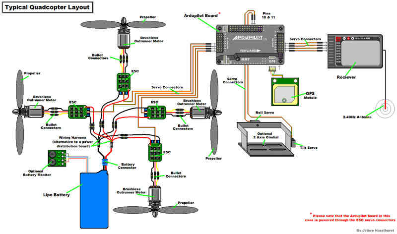
PPTX Slide 1 Functional Diagram of the MSP430F5529 & CC3100. SPI. Flight Controller (APM 2.8)-Nerve center of Drone. Why APM? Open source project from 3DRobotics "cinema flying" and "autonomous flying" ... Calibrating APM 2.8 using Mission Planner | step to ... Firstly, select on frame type, and select the X type of frame for your Quadcopter. Now go to the Accel Calibration Section and click on Calibrate Accel. Follow the instructions as shown on screen and perform the same to calibrate the Accelerometer. After finishing the accelerometer calibration, you can head for compass calibration. Arducopter 2.8 Wiring - Wiring Diagrams This guide will show you all the cables and parts that you will need to connect to your arducopter. Typical Quadcopter Layout. Connect ESCs and Motors In most cases problems are due to incorrect wiring. Always connect signal and ground. Check your ESC type to decide how to connect the +5V line.
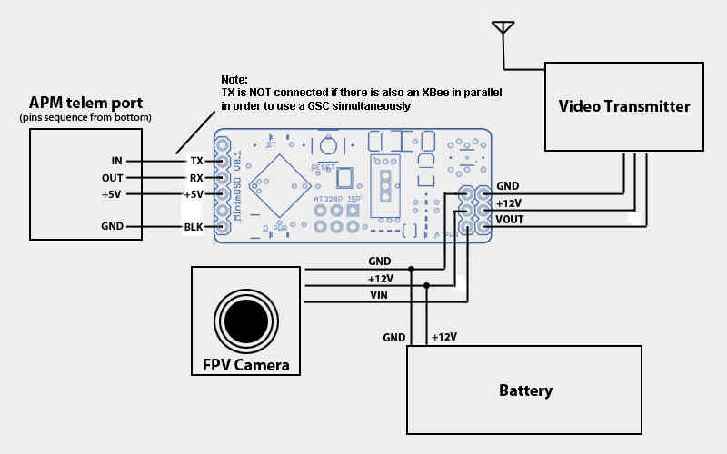
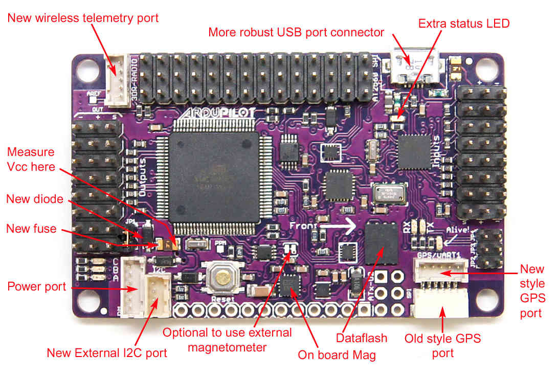
Apm 2.8 wiring diagram. en.wikipedia.org › wiki › Central_processing_unitCentral processing unit - Wikipedia Block diagram of a basic uniprocessor-CPU computer. Black lines indicate data flow, whereas red lines indicate control flow; arrows indicate flow directions. Hardwired into a CPU's circuitry is a set of basic operations it can perform, called an instruction set . APM 2.8 wiring (camera switch, OSD, VTX, step down, UBEC ... APM 2.8 wiring (camera switch, OSD, VTX, step down, UBEC) I have been researching this stuff for a couple of months now and decided to look into my specific build a little more, I just want to know your inputs on my setup and if I am missing something. (I don't want to blow up my APM) X8R to APM 2.8 wiring hookup - RC Groups X8R to APM 2.8 wiring hookup. Hi guys, first time posting here. I could use some help with wiring my APM 2.8 to a FrSky X8R receiver. I've been searching for what feels like forever on the internet/ YouTube and have details on hooking up everything from a Naze 32 to Pixhawk but nothing for my specific setup. Making of Drone - SlideShare 39 APM 2.8 Fig.6. (b) Above Fig 6. (b) is shown the APM 2.8 flight controller protection packing. APM 2.8 will contain some of meters which are used to control the vehicle when the it is in air, if don not provide this type of protection to APM 2.8 the drone (quad copter) may be chance to misbehaver with us or irresponsive to our controllers.
Building Your First ArduCopter : 9 Steps (with Pictures ... Wiring the ESC'S with APM You would have four wires from all the esc's (one for each). Refer to Part 4 picture for arm's number . The first arm's (front-right) esc goes to Pin 1 in the OUTPUT section. The second arms's (back-left) esc goes to Pin 2 in the OUTPUT section. The thrid arm's (front-left) esc goes to Pin 3 in the OUTPUT section. Apm 2.8 manual - Carol Romine This guide will show you all the cables and parts that you will need 29 Jan 2014 2.2.2 Arducopter frame, power distribution and motors . . . . . . . 8. 3 Qualysis suggest you exploit datasheets and manuals for the specific piece, that can be easily found online. . Figure 2.8: Battery charger. 3. Press Batt. auto1x1.de › sdp-malfunction-2020-volvo-truckauto1x1.de Sdp malfunction 2020 volvo truck 2001 Dyna Wiring Diagram Wiring diagram sheets detail. 2001 harley dyna wiring diagram i absolutely love this motor and speed control combination for the price i put these on my f450 quadcopter frame with apm 2 8 flight controller and it dialed in. Collection of harley ignition switch wiring diagram. Bikez biz has an efficient motorcycle classifieds.
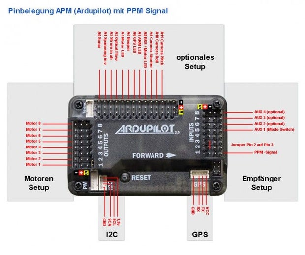
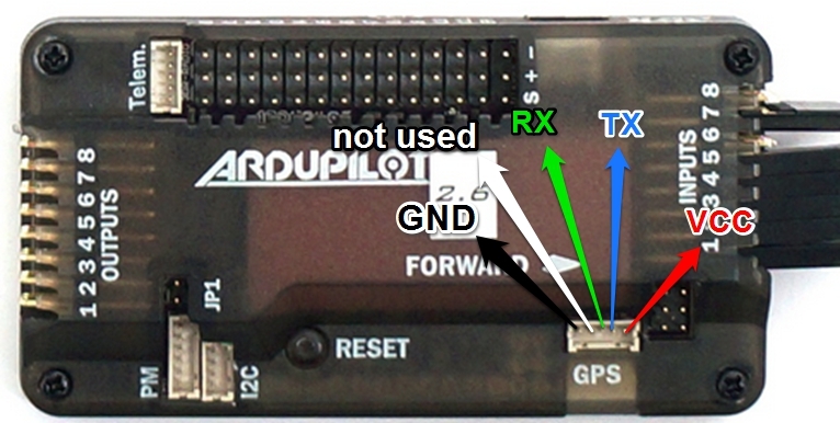
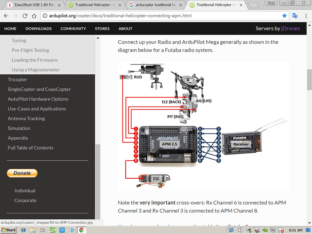
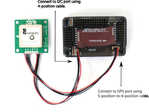
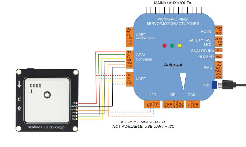
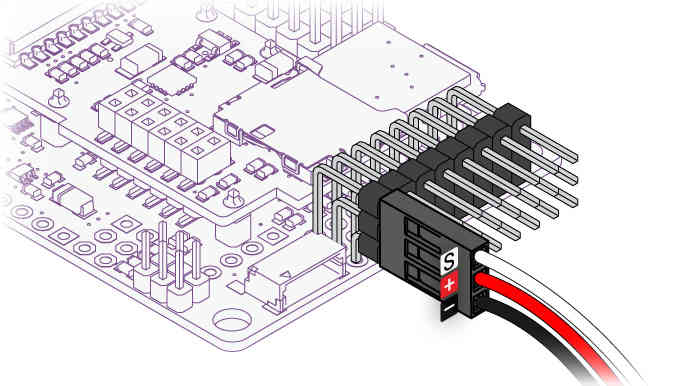
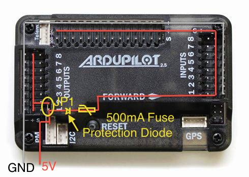
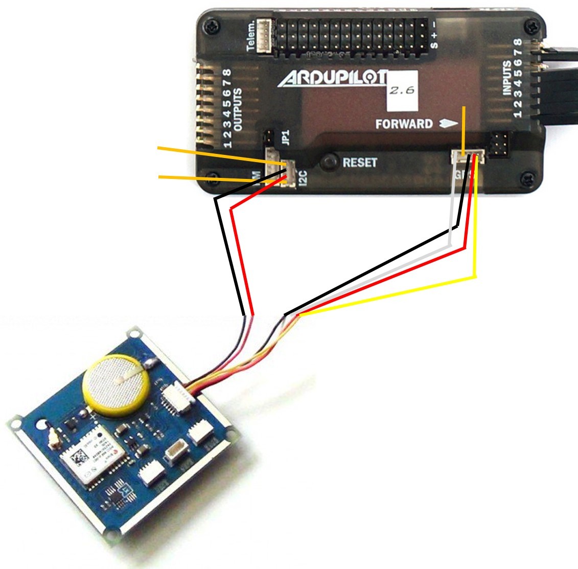
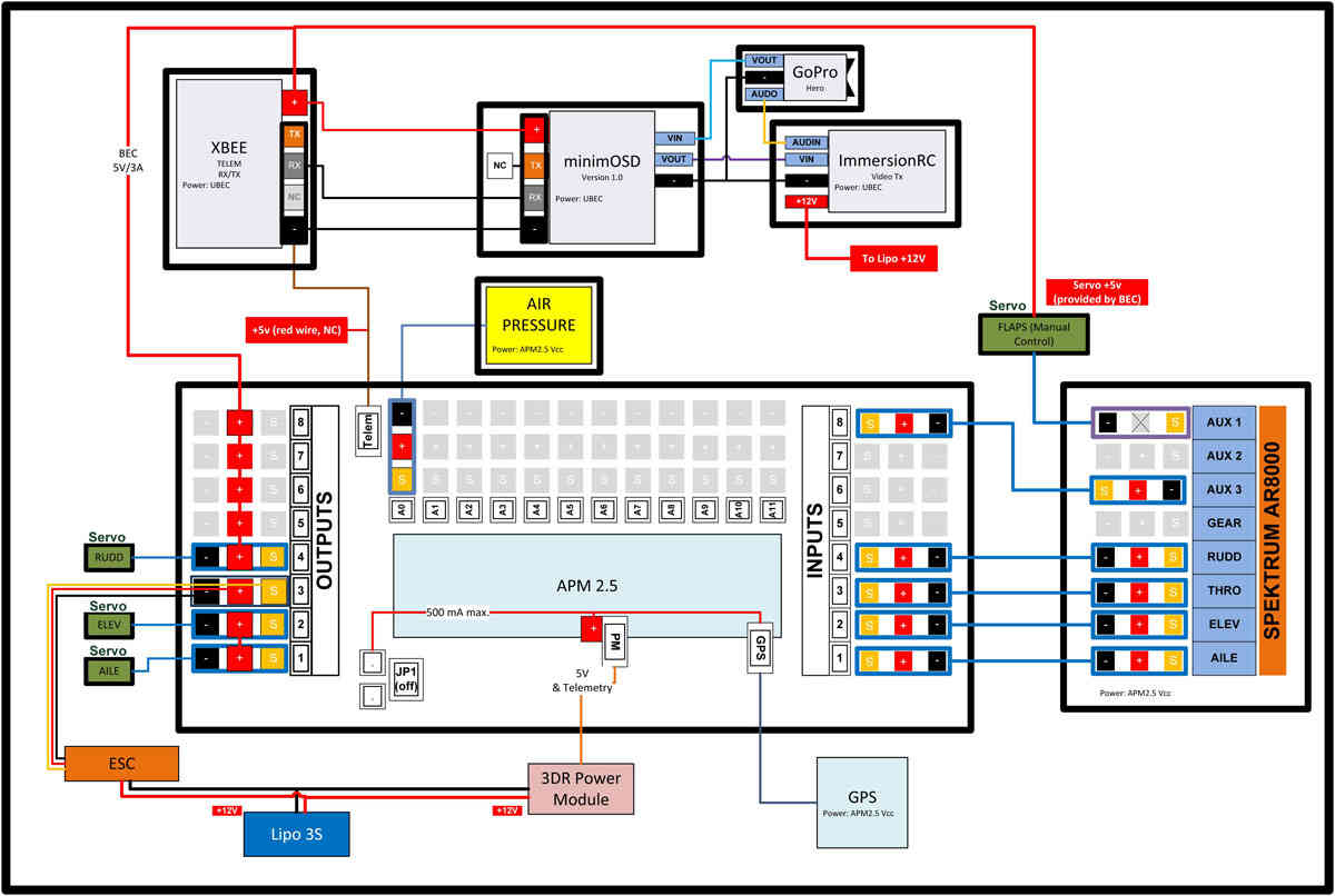
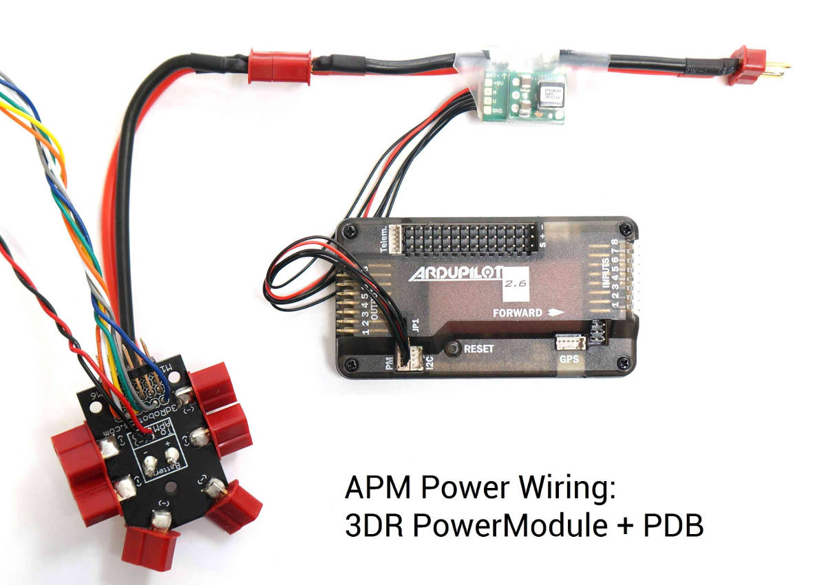
Apm 2.8 Wiring Diagram - schematron.org Apm 2.8 Wiring Diagram 27.11.2018 5 Comments Auto Pilot RC Drone - ArduPilot APM ArduPilot APM Connect the ArduPilot APM to the computer via USB cable. APM Wiring Diagram. The diagram below is an overview of how an APM2 can be connected to a to APM Output Signal pins with the M1 wire connecting to the signal pin labeled 1. APM 2.8 and GPS / Compass - Discussions - diydrones Hi, I've done lots of thread-searching but haven't found a fix; any help would be appreciated. I am in the process of upgrading from APM 2.5 to APM 2.8. My problem is that I cannot get the GPS / Compass to work. It is (they are) a Ublox Neo module(s). The MAG jumper next to the GPS connector is removed but even with it place I get 'Bad compass health' in Mission Planner. I have plugged in two ... Arducopter APM 2.9 SBUS Support 2.6 2.8 Upgraded Flight ... APM2.9 is used in the same way as APM2.6, 2.8. The benefit is that APM 2.9 supports SBUS receiver protocols. Why use the SBUS protocol? The communication speed is fast, the wiring is simple, only one line is needed, unlike each channel of the PWM, the PWM communication speed is slower than SBUS. Archived:APM2.x Wiring QuickStart — Copter documentation The diagram below is an overview of how an APM2 can be connected to a receiver, ESC, GPS and even a camera gimbal. Powering the autopilot The easiest way to power the APM2.x is using a 3DR Power Module with a LiPo battery. To wire a power module, connect the red-and-black two wire cable on the power module to the PDB red and black two-wire.
Apm Flight Controller - 15 images - cx20 252 to apm 2 8 ... [Apm Flight Controller] - 15 images - apm 2 8 internal compass without external compass compass, buy apm 2 8 basic flight controller kit with gps module at, new apm2 6 flight controller board for multicopter, which flight controller should you choose flite test,
Arducopter v2.8 won't connect to Mission Planner - reddit level 1. · 4 yr. ago. If APM 2.8 power up with USB cable plugged, it means that you have driver missing in your operating system: check this video if can help. Anyway, if the above one is your case, try also changing usb cable: the one that is used for hard drive is ok..don't use the one for camera.
APM Quadcopter Setup : 4 Steps - Instructables I have apm 2.8 and ublox neo 6m gps without compass module, many of the experts and sites says that neo 6m gps is not compatible with apm 2.8. Can you please explain it to me or help me in getting it work as it is actually not recognised by apm 2.8 while I am trying it.
Nơi bán Apm 2 8 giá rẻ, uy tín, chất lượng nhất Power Module Current Module Female Male Plug with 5.3V DC BEC for APM 2.8 PIXHAWK Flight Controller APM2.6 2.5 2.52 RC DIY Drone Accessories. 550.000 đ -44 % Nơi bán: Hồ Chí Minh, Toàn Quốc.
Arducopter 2.8 Wiring - Wiring Diagram Pictures Signal goes on the top of the rail (white or orange color wire) and ground at the.Connect the PDB multi-wire cable to APM Output Signal pins with the M1 wire connecting to the signal pin labeled 1, M6 and signal pin 6, etc. See the above link for additional detail. The Power Module will not power servos and other peripherals.
ReadytoFlyer 2.8 The ReadytoFlyer / APM 2.8 is a complete open source autopilot system. It allows the user to turn any fixed, rotary wing or multirotor vehicle (even cars and boats) into a fully autonomous vehicle; capable of performing programmed GPS missions with waypoints. This version comes with the RC/Servo connectors unsoldered, so you can choose between ...
(1/8) APM 2.5/2.6/2.7/2.8 - Simple installation and setup ... In this video we cover -- • What you'll need • Selecting and installing the firmware • Calibration of the magnetometer and accelerometers • Connection to the radio receiver • Calibration of the RC...
downloads.cs.stanford.edu › nlp › dataStanford University UNK the , . of and in " a to was is ) ( for as on by he with 's that at from his it an were are which this also be has or : had first one their its new after but who not they have – ; her she ' two been other when there all % during into school time may years more most only over city some world would where later up such used many can state about national out known university united then made ...
Turnigy 9x Receiver Wiring - Wiring Diagrams Free Turnigy 9x Receiver Wiring. Help! Connecting the Turnigy 9x receiver Multirotor Drone Talk. First, I recommended you try if it works! Connect all channels as you can see in the picture. PPM encoder pinout for sure: INPUT: 1) GND - black. 2) 5V - red. I need to know how to use the channels when connecting the ECS and Servos to a Turnigy 9X Receiver?
APM2.8 Flight Controller Board For RC Multicopter ... - eBay APM 2.8 Flight Control Controller Board APM2.8 ArduPilot Mega Side Pin f/ QAV250. $32.29. $33.99 previous price $33.99 previous price $33.99 + $3.70 shipping + $3.70 shipping + $3.70 shipping. Picture Information. Image not available. Mouse over to Zoom- Click to enlarge. Hover to zoom ...
PDF Wiring Diagrams Wiring Diagrams The drawings are arranged in numerical order on the following pages. Description Drawing Number Page Point-to-Point Wiring Diagram GM63943 Sheet 1 12 Sheet 2 13 Schematic Diagram ADV-7602 Sheet 1 7 Sheet 2 8 4-Lead, Single-Phase Voltage Connection ADV-5875A-H 5 12-Lead, Single-Phase, Three-Phase Voltage Connection ADV-5875B-H 6 ...
Apm 2 8 Pinout - pin on drones, apm2 5 2 schematic updated ... apm 2 8 wiring diagram. Apm 2 8 Pinout. Here are a number of highest rated Apm 2 8 Pinout pictures upon internet. We identified it from trustworthy source. Its submitted by doling out in the best field. We understand this kind of Apm 2 8 Pinout graphic could possibly be the most trending subject similar to we ration it in google lead or facebook.
Apm 2 8 Flight Controller Wiring Diagram - 15 images - apm ... [Apm 2 8 Flight Controller Wiring Diagram] - 15 images - archived apm2 x wiring quickstart plane documentation, omnibus f3 aio quickstart guide guides dronetrest, pin on arducopter, pixhawk 6 9 3dr ublox gps compass,
Legal - Trend Micro Select the terms and conditions that apply to your use of Trend Micro products and services. If you have another agreement directly with Trend Micro, that agreement will control your use of the products and/or services.
(2/8) APM 2.5/2.6 - Powering the board, motor installation ... In this second video in the APM 2.X series we look at how to mount the board, how it's powered, how to install the motors and calibrate the ESCs and perform ...
Arducopter 2.8 Wiring - Wiring Diagrams This guide will show you all the cables and parts that you will need to connect to your arducopter. Typical Quadcopter Layout. Connect ESCs and Motors In most cases problems are due to incorrect wiring. Always connect signal and ground. Check your ESC type to decide how to connect the +5V line.
Calibrating APM 2.8 using Mission Planner | step to ... Firstly, select on frame type, and select the X type of frame for your Quadcopter. Now go to the Accel Calibration Section and click on Calibrate Accel. Follow the instructions as shown on screen and perform the same to calibrate the Accelerometer. After finishing the accelerometer calibration, you can head for compass calibration.
PPTX Slide 1 Functional Diagram of the MSP430F5529 & CC3100. SPI. Flight Controller (APM 2.8)-Nerve center of Drone. Why APM? Open source project from 3DRobotics "cinema flying" and "autonomous flying" ...










Comments
Post a Comment