43 map sensor wiring diagram engine
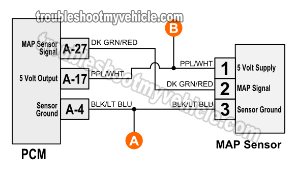
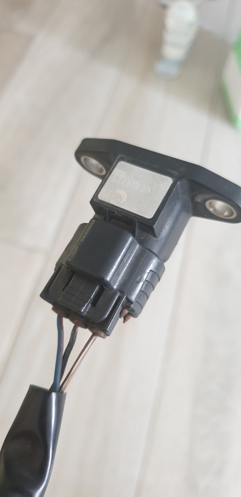
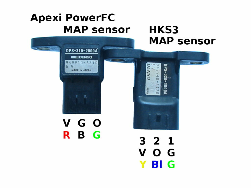
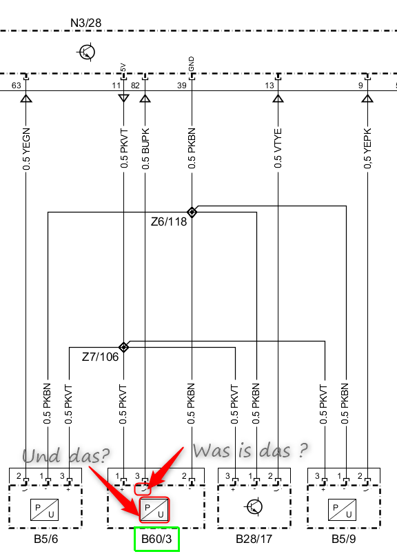
MAP sensor MAP sensor. circuits diagram wiring free electronic schematic design plans schema DIY projects handbook guide tutorial schematico electrónico schématique diagrama esquemático projeto elektronisch schematisch schaltplan schematy circuito shema схема skematisk Schaltbild schematisk... MAP and MAF sensor wiring diagram | Forum For the MAP sensor you can test the wires with a multimeter... it will be obvious which ones are ground and +5v. looking into the stock map sensor (not the plug) the left one is ground and the right is the power supply which leaves the middle as the signal.
MAP Sensor & Wiring Diagram | Map sensor, Automotive repair, Car... Подписаться. MAP Sensor & Wiring Diagram. О видео. Покупки. Engine codes, are recorded, by the (OBD) computer system. Mostly, issues that result in, harmful and polluting emissions, from exhaust gases.
Map sensor wiring diagram engine
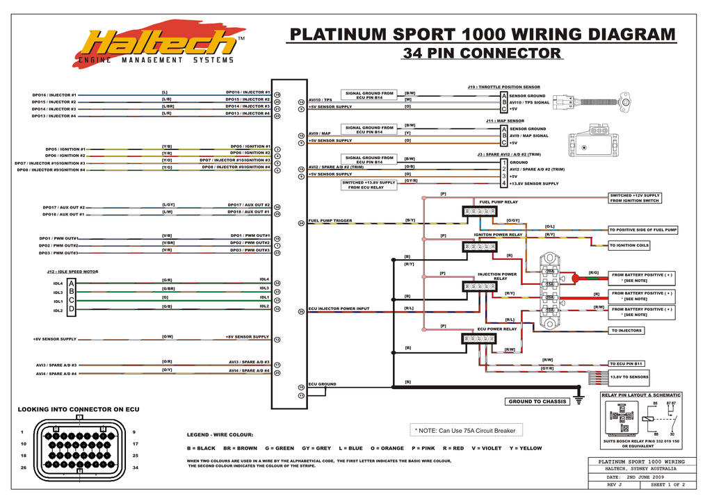
Making sense of your sensors: MAP sensor | Delphi Auto Parts A faulty MAP sensor will affect an engine's air-fuel ratio. If the ratio is incorrect, ignition inside the engine will occur at an improper time in the combustion Consult the manufacturer's service manual to identify the signal, ground, and 5-volt reference and back-probe the wires. Turn the ignition switch on... PDF Formula SAE Race Car Electrical | Crankshaft Position Sensor The wiring harness ties the engine sensor outputs to the ECU for signal processing and sends From this diagram, a number of systems were implemented and integrated in order to work with Figure 2: Haltech wiring map. Note the high number of NC's or "no connects" as the vehicle uses a... 3Bar Map Sensor Wiring Diagram | Manualzz User manual | 3Bar Map Sensor Wiring Diagram. Twin Tec 3BarGuide Map Sensor Installation CAUTION: CAREFULLY READ INSTRUCTIONS BEFORE Leave the factory TMAP sensor in place. Cable drive applications would install in the same fashion but will not have an IAT signal wire.
Map sensor wiring diagram engine. Sensor Wiring Diagrams - Microtech EFI Engine Management. Eq. Equalizer Manual & Wiring Diagram. Input 8. Load Map. logger kit. LT-32c Wiring Diagrams. Sensor Wiring Diagrams. Universal TPS Wiring Diagram. 60-2 Trigger Kit Diagram. PDF Document Three-Wire Sensors (MAP, TP and FP). The following figure shows a schematic representation of a 3-wire sensor. All 3-wire sensors have a reference The system monitors the sensors incorporated on the engine and if a malfunction is discovered a fault description is stored in the PCM and available... 3-Bar MAP sensor Wiring Diagram. physically adapt the sensor to the MegaSquirt® PCB by comparing pin-outs and fabricating wires, daughter boards, or whatever else is needed For example, the 3-bar GM MAP sensors can be adapted to MegaSquirt. They use a 5 volt reference, just like MegaSquirt. Oxygen Sensor: 1, 2, 3, 4 Wire O2 Sensor Wiring Diagram Oxygen sensor also called O2 Sensor or lambda sensor (λ) is an electronic sensor that measures how many oxygen molecules are present in the exhaust gas, which helps the ECU monitor the engine performance. • Easily Master 3 & 4 Pin MAP Sensor Wiring Diagram In 2 Min.
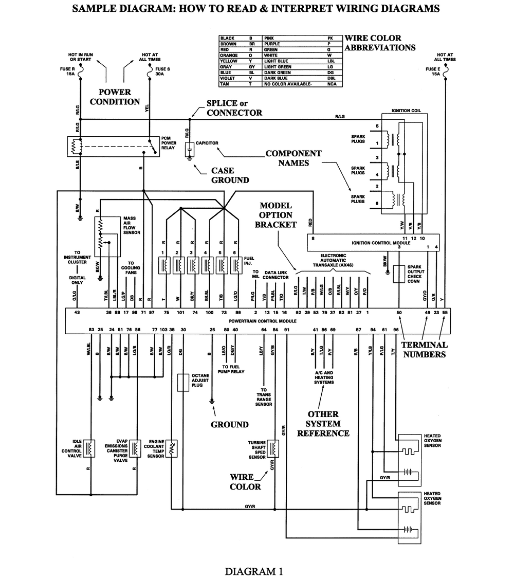
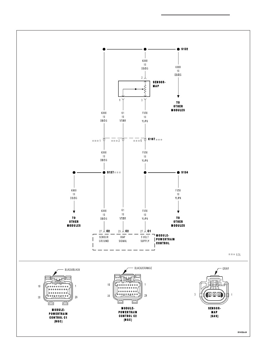
Map Sensor Wiring Diagram | autocardesign Map Sensor Wiring Diagram- wiring diagram is a simplified tolerable pictorial representation of an electrical circuit. 2001 dodge durango map sensor wiring diagram diagram database reg repair guides electronic engine controls manifold absolute. toyota map sensor pinout #5 | Map sensor, Electrical circuit diagram... MAP Sensor & Wiring Diagram - … 19.01.2011 MAP Sensor & Wiring Diagram ADPTraining. Subscribe Subscribed Unsubscribe 76,036 76K. ... RENAULT LAGUNA WIRING DIAGRAMS Pdf Download | ManualsLib Diagram 1 Information for wiring diagrams. Diagram 2 Starting, charging, Diesel fuel shut-off, engine cooling fan. Page 7 Wire colours Key to items Diagram 6 BA White JA Yellow Battery 67 Ignition power module 74 Knock sensor Ignition switch 68 Fuel pump relay 75 MAP sensor BE Blue MA... Map Sensor Wiring Diagram Map Sensor Wiring Diagram. January 18, 2019January 18, 2019. Sponsored links. Post navigation. Bmw 325i Engine Diagram. 2006 Chevy Aveo Ls.
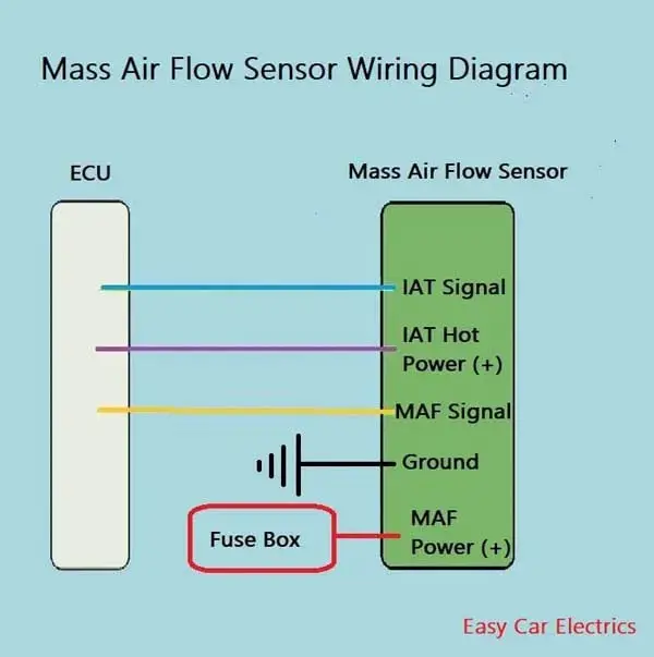
A Simple MAP/MAF Enhancer | Two Types of Sensor A MAP sensor measures the pressure in your intake manifold. MAF = Mass Air Flow. Even if you find your signal wire using a diagram, you should still test it before proceeding. You must make sure that you see a voltage change when you rev the engine, and that the voltage drops back down when... MAP sensor - Wikipedia The manifold absolute pressure sensor (MAP sensor) is one of the sensors used in an internal combustion engine's electronic control system. Engines that use a MAP sensor are typically fuel injected. 1993-1995 MAP Sensor Wiring Diagram (Jeep Grand Cherokee 4.0L) MAP Sensor Wiring Diagram (1993-1995 4.0L Jeep Grand Cherokee). Here, in a nutshell is how the MAP sensor works: Once the MAP sensor is 'On' and the engine is running, it creates a decreasing voltage signal as the intake manifold vacuum increases (like when the engine is under... Wiring and Sensors External Wiring Schematic. (This wiring diagram is for those creating their own harness for a V2.2 Thus the injectors might stay open and flood the engine if the MegaSquirt® controller isn't powered Note that the external wiring diagram in this Sensors and Wiring section is entirely separate from...
MAP Sensor & Wiring Diagram, Видео, Смотреть онлайн The MAP sensor or manifold air pressure sensor is a main input to the ECM or engine control module. Get the scoop on the MAP sensor from an electronic point of view and towards reading wiring diagrams.
Part 1 -How to Test the MAP Sensor (4.7L Dodge Dakota, Durango) Symptoms of a BAD MAP Sensor. Checking the MAP Sensor Signal With a Multimeter. The two most obvious symptoms of a bad MAP sensor is that the check engine light will be shining nice and bright and that the engine Ignition System Wiring Diagram (2002 4.7L Dodge Dakota And Durango).
MAP sensor measurement To help determining whether a MAP sensor is functioning correctly, different possible deviations from the Figure 3 shows a waveform of a MAP sensor of a car with running engine. Signal shows a lot of noise: Cause: wiring of signal or power supply damaged, poor connection in connector terminals.
Map sensor wire diagram 202 Isuzu Ftr Wiring Diagram Map_sensor_wire_diagram%202 Isuzu Ftr Wi. JPG Image 39.6 KB. i have a 1994 isuzu fsr 32 with a 6he1 engine what manual with wiring diagrams do i need.
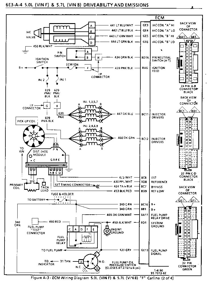
Wiring Diagrams | PDF | Fuel Injection | Ignition System wiring-diagrams.pdf - Free download as PDF File (.pdf), Text File (.txt) or read online for free. Fuel Pump Distributor Coil Electronic Spark Control (KS) Module Data Link Connector (DLC) Manifold Absolute Pressure (MAP) Sensor Idle Air Control (IAC) Throttle Position (TP) Sensor Engine Coolant...
How To Test a Dodge Neon MAP Sensor - My Pro Street The Neon MAP Sensor is mounted to your intake manifold in your 2.0 liter Dodge engine. This sensor plays a huge part in determining engine load by reading the air pressure in your intake Unplug the three pin unit and gently probe the front of PIN B as shown in our Neon MAP Sensor wiring diagram.
Chapter 9. Sensors | Figure 9.4. Secondary Hall sensor wiring diagram Primary VR sensor. VR sensors have two wires (and often a 3rd (shield)). The polarity must be known. Figure 9.2. Primary Hall sensor wiring diagram. Secondary VR sensor. EC18-pin12 VR+ An entire engine cycle of 720 (real) degrees must be scaled down to no more than 255 (decimal).
3Bar Map Sensor Wiring Diagram | Manualzz User manual | 3Bar Map Sensor Wiring Diagram. Twin Tec 3BarGuide Map Sensor Installation CAUTION: CAREFULLY READ INSTRUCTIONS BEFORE Leave the factory TMAP sensor in place. Cable drive applications would install in the same fashion but will not have an IAT signal wire.
PDF Formula SAE Race Car Electrical | Crankshaft Position Sensor The wiring harness ties the engine sensor outputs to the ECU for signal processing and sends From this diagram, a number of systems were implemented and integrated in order to work with Figure 2: Haltech wiring map. Note the high number of NC's or "no connects" as the vehicle uses a...
Making sense of your sensors: MAP sensor | Delphi Auto Parts A faulty MAP sensor will affect an engine's air-fuel ratio. If the ratio is incorrect, ignition inside the engine will occur at an improper time in the combustion Consult the manufacturer's service manual to identify the signal, ground, and 5-volt reference and back-probe the wires. Turn the ignition switch on...















Comments
Post a Comment