41 ddec 4 ecm wiring diagram
Ddec IV Oem Wiring Diagram PDF | PDF | Electrical ... 110351855-Ddec-IV-Oem-Wiring-Diagram.pdf - Free download as PDF File (.pdf), Text File (.txt) or read online for free. Scribd is the world's largest social reading and publishing site. Open navigation menu PDF Specifications - Wanderlodge Owners Group Fig. 4, Detroit Diesel Series 50 and 60 Engines With DDEC III Wiring Diagram (engine-harness side) 54.17 Detroit Diesel Electronic Controls (DDEC ® ) Wiring 400/4 Heavy-Duty Trucks Service Manual, Supplement 23, December 1999
Detroit DDEC 3 & 4 Wire Diagram | TruckManuals.com Detroit DDEC 3 & 4 Wire Diagram quantity. Add to cart. SKU: TMDD0007-WD Category: Detroit Diesel Wire Diagrams. Description. Reviews (0) Laminated factory Detroit Diesel DDEC 3 & 4 ECM wire diagram. Shows ECM & wiring to & from the ECM. Includes connections, wires, sensors, input & controlled devices. Excellent for diagnostics.
Ddec 4 ecm wiring diagram
Detroit Ddec 4 Ecm Wiring Diagram | autocardesign Detroit Ddec 4 Ecm Wiring Diagram - wiring diagram is a simplified within acceptable limits pictorial representation of an electrical circuit. It shows the components of the circuit as simplified shapes, and the capability and signal connections along with the devices. Detroit DDEC 4 Wire Diagram Chart | TruckManuals.com Laminated factory Detroit Diesel DDEC 4 ECM wire diagram. Shows ECM & wiring to & from the ECM. Includes connections, wires, sensors, input & controlled devices. Excellent for diagnostics. Laminated factory Detroit Diesel DDEC 4 ECM wire diagram. For 2003 & newer DDEC 4 EGR engines. Included: ECM ECM wiring Connections Wires Sensors Ddec 3 Ecm Wiring Diagram 3 for partial (detailed) views of the full view of the DDEC II wiring diagram. See Fig. 4 for a full view of the DDEC III wiring diagram (the engine side)/5(11).Ddec 3 Wiring Diagram Incredible 4 Ecm - diagramweb.netSchematic Diagram of DDEC II | Detroit Diesel Troubleshooting Diagrams.
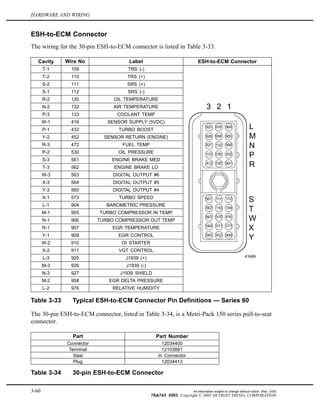
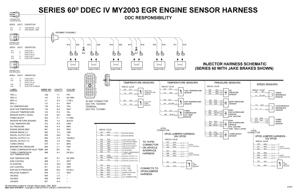
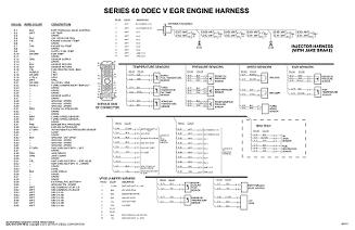
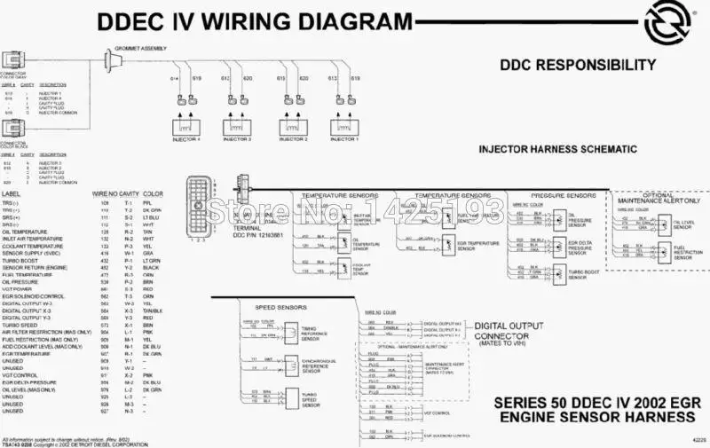
Ddec 4 ecm wiring diagram. Ddec V Wiring Diagram DDEC V WIRING DIAGRAM PIN NO. WIRE COLOR DESCRIPTION PIN NO 1 COLOR WHT DESCRIPTION INJ COMMON 1,2,3 GROMMET ASSEMBLY DDC. Diagrama De Cabina Oem Ddec V 10 3 Vi Wiring Diagram 5 Wikiduh Com With 4 Ecm. 14 ddec 4 ecm wiring diagram car cable and detroit diesel series 60 best. DDEC V provides an indication of engine and vehicle malfunctions. Detroit Diesel Engines PDF Service Repair Manuals ... Aug 09, 2018 · Detroit Diesel DDEC II and III Wiring Diagrams.pdf: 993.1kb: Download: Detroit Diesel DDEC III-IV Series 60 Injector Harness Schematic Wiring diagram.png: 350.1kb: Download: Detroit Diesel DDEC IV Series 60 MY2003 EGR engine sensor harness Wiring Diagram.png: 308.7kb: Download: Detroit Diesel DDEC IV Series 60 MY2003 EGR Vehicle Interface ... PDF Kenworth Wiring Diagram Ddec 4 Engine wiring diagram HOW AN ALTERNATOR WORKS PART FOURAll About 7-Pin RV Trailer Wiring Detroit series 60 idle shut down disable-Detroit Diesel DIagnostic Link Power Door Locks \u0026 Wiring Diagram Detroit 12.7 EGR DDEC IV The ECM Lab - The Detroit Diesel Series 60 DDEC IV ECM Detroit wiring harness Kenworth Wiring Diagram Ddec 4 PDF 3 HARDWARE AND WIRING - Wanderlodge Owners Group HARDWARE AND WIRING MCM 120-pin Connector for Series 60 Engines The pinouts for the 120-pin connector for the Series 60 engine are listed in Table 3-1, Table 3-2, Table 3-3, and Table 3-4. Pin Signal Type Function Connector 1RPU_H NC 2RPU_LNC 3 PV_IM1 NC 4 MV_B5F Spill Control Valve (cyl 4) - pin 4 5 MV_B5 Spill Control Valve Common - pin 3
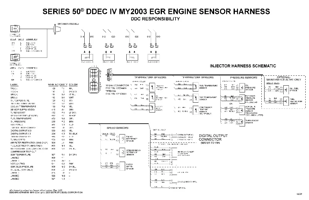
publimaxstore.it 2 days ago · Dec 01, 2015 · Oil light: Indicates a severe drop in oil pressure. The dash lights and cig lighter were out but it world reboot the whole instrument panel every few hundred miles or so completely shutting down before reboot. Detroit DA-RT-4. If the light doesn't go off consult your Volkswagen Retailer. Wiring, connectors, ignition coil 5, ECM. 14 Ddec 4 Ecm Wiring Diagram Car Cable And Detroit Diesel ... May 15, 2019 - 14 Ddec 4 Ecm Wiring Diagram Car Cable And Detroit Diesel Series 60 On Detroit Diesel Series 60 Ecm Wiring, best images 14 Ddec 4 Ecm Wiring Diagram Car Cable And Detroit Diesel Series 60 On Detroit Diesel Series 60 Ecm Wiring Added on Wiring Diagram - floraoflangkawi.org Ddec 2 Ecm Wiring Diagram - schematron.org See Fig. 4 for a full view of the DDEC III wiring diagram (the engine side). See Fig. 5 and Fig. 6 for partial (detailed) views of the full view of the DDEC III wiring diagram (the engine side)/5(11). The replaceable PROM is an EPROM in the DDEC II ECM. The ECM has isolator mounts for both vibration and electrical isolation. PDF dmbruss.com 92.4 INJECTOR HARNESS WIRING SCHEMATIC - 8V149 ENGINES DDEC TROUBLESHOOTING MANUAL SERIES 8V92 AND 31484 92-7 The following wire schematics support the injector harness; see Figure 92-5. oo Figure 92—5 00000 00000 Injector Harness — U.' O o 00000 00000 aaogv Series 8V92 and 8V149 Engines All information subject to change without notice.
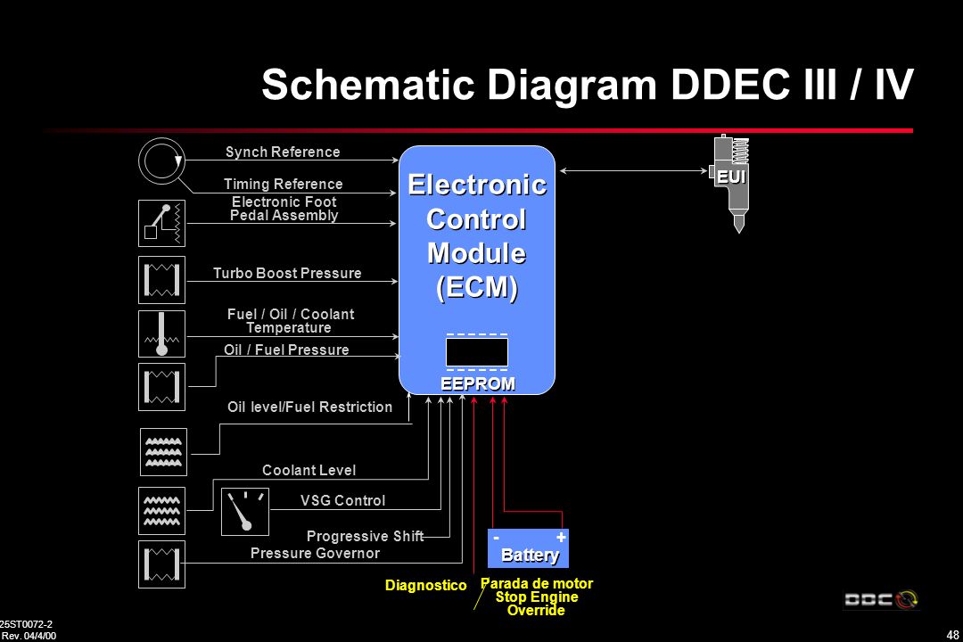
PDF Detroit Diesel Series 60 Ecm Wiring Diagram Detroit Series 60 Ecm Wiring Diagram | Free Wiring Diagram The Electronic Control Module (ECM) is the backbone for engine management. The ECM receives electronic inputs during vehicle operation via engine and vehicle mounted sensors. Refer to Appendix "10.4.7 DDEC IV ECM Overview and Vehicle Collections of Detroit Ddec 4 Ecm Wiring Diagram Detroit Ddec 4 Ecm Wiring Diagram- wiring diagram is a simplified within acceptable limits pictorial representation of an electrical circuit.It shows the components of the circuit as simplified shapes, and the capability and signal connections along with the devices. PDF Detroit Diesel Series 60 Ecm Wiring Diagram Ddec Iv Ecm Wiring Diagram - schematron.org DDEC III/IV Electronic Control Module. DDEC III/IV provides an indication of engine and vehicle malfunctions. The ECM continually monitors the DDEC III/IV system. See Figure "DDEC III/IV System Series 60 Diesel Engine" and see Figure "DDEC III/IV System Series 60 Natural Gas Engine". PDF DDEC IV - f01.justanswer.com wire no. 115 953 cavity a b 280 series metri-pack connector ddc p/n: 15300027 coolant level probe 3/8 in. nptf ddc p/n: 23520381 1/4 in. nptf ddc p/n: 23520380 9/16 in. nptf ddc p/n: 23522855 color orn blk/wht coolant level sensor stop engine light red rd check engine light yellow ye wire no. 509 419 +12/24vdc color ppl ppl/wht instrument panel ...
Detroit Diesel Training Center Would Like to Thank Dan Clark ...
comparative cultural studies comparative ... - Purdue University Issue 6.1 (March 2004) Thematic Issue: Shakespeare on Film in Asia and Hollywood. Ed. Charles S. Ross
NWSTP
Ddec 111 Wiring Diagram - Wiring Tech 14 Ddec 4 Ecm Wiring Diagram Car Cable And Detroit Diesel Series 60 On Detroit Diesel Series 60 Ecm Wiring Detroit Diesel Dodge Ram Diesel House Wiring . Detroit Diesel Epa Ddec Meb Series50 60 Wiring Diagrams Manual 2003 Auto Repair Manual Forum Heavy Equipment Forums Download Repair Workshop Manual .
Series 60 EGR - Section 10.4.7 DDEC IV Wiring Schematics ...
Ddec Iv Ecm Wiring Diagram - schematron.org The DDEC II ECM . Ddec 3 ecm wiring diagram along with 60 series ddec iii wiring diagram also ddec 5 ecm wiring diagram along with diagramm ofenverkabelung ge jbp68hd1cc in addition misfiring cylinder together with 60 series injector wiring harness also carrier ac parts diagram as well as kenworth t trailer wiring diagram further atv wiring ...

Detroit Diesel EPA-DDEC-MEB-Series50-60 Wiring Diagrams ...
Ecm Wiring Diagram - easywiring One ecm is called the master while the others are referred to as receivers. The detroit diesel series 60 ddec iii iv v vi wiring diagrams are also known as electrical schematics or circuit diagrams. Engine Sensor Locations On A Detroit Dd13 Get Free Image Freightliner Detroit Engineering Here is a simple wiring diagram for …
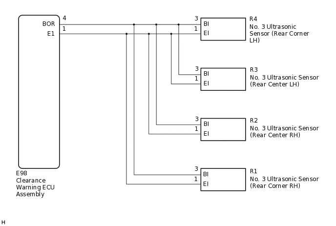
TOYOTA PARKING ASSIST-SENSOR SYSTEM(for Hatchback ...
PDF 3 HARDWARE AND WIRING - Wanderlodge Gurus 3.2.2 ECM PART NUMBERS Part numbers for DDEC III and IV ECMs are listed in Table 3-3. Part Number Description Voltage No. of Cylinders 23518645* DDEC III - Standard On-highway ECM 12/24 V 6 23518743 DDEC III - Universal ECM 12/24 V 8 23518744 DDEC III - Series 4000 ECM only 24 V 8 23519307 DDEC IV - Standard On-highway ECM 12 V 6

Series 60 EGR - Section 10.4.7 DDEC IV ECM Overview and ...
Ddec 5 Ecm Wiring Diagram The 1st is a wiring diagram dash to sensors, or sensors to dash lights. However you want to look at it. Unless you can point out the actual location of the VPODS to ECM. Ddec 5 Ecm Wiring Diagram (Nov 24, ) ― This best photo collections about ddec 5 ecm wiring diagram is available to save.
Ddec iv on highway - egr application and installation
Detroit Series 60 Ecm Wiring Diagram - Wiring Diagram Ddec Iv Wiring Diagram. Detroit Diesel Series 60 Diagram, Bar - Detroit Series 60 Ecm Wiring Diagram. Wiring Diagram comes with a number of easy to stick to Wiring Diagram Directions. It's intended to aid each of the common person in building a proper program. These directions will probably be easy to comprehend and implement.

Detroit Series 60 12.7L DDEC IV ECM / ECU For Sale | Opa ...
PDF Ddeciv.pdf - Ddec Iv Application and Installation Manual precuations, followed by hardware and wiring requirements, inputs and outputs, and available features. The second portion covers communication protocol. The third portion covers the tools capable of obtaining engine data and diagnostic information from the Electronic Control Module, as well as reprogramming of its key parameters.
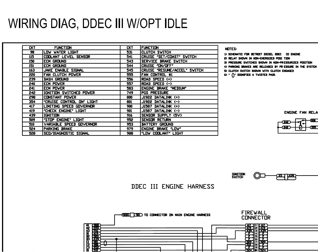
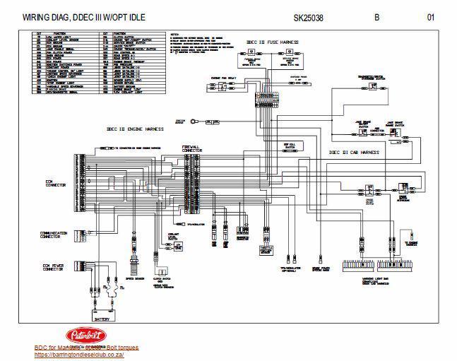
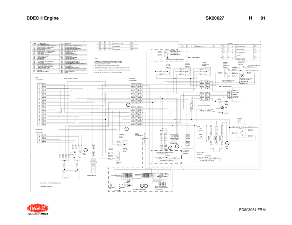
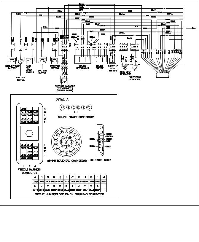
Peterbilt DDEC III W/OPT IDLE Wiring Diag Manual
PDF DDEC II Engine - Supermiller ecm connector ecm power connector a543 555 p 541 p 542 544 545 p 901 916 952 953 a543 555 902 541 p 542 ... 4 1 7 9 5 2 9 5 2 4 1 7 1 6 throttle position sensor 68 a150 150 115 68 531 a543 558 439 b b b 68 531 a543 ... service brakes on parking brakes on service brakes off a150 150 115 439 439 b ddec ii coolant level control module 4 39 p 2 29 ...
Detroit Diesel DDEC II Engine Electrical Wiring Diagrams
laserenissimavenezia.it Feb 28, 2022 · Nov 22, 2010 · here is the deal,run jumper wire at diagnostic connection but instead of first 2 slots ,go with 1 and 4,if check engine light comes on ,its the circuit board in module under dash,its about 2 inches wide,4 inches long,either lite green or gray or black,plastic tube box with a door on one end,will be tape up alongside wiring,cut ...

Series 60 - CRUISE CONTROL - DDEC VI SCHEMATICS - Detroit ...
ingenieurbuero-edgar-pech.de Feb 19, 2022 · The Cummins Signature, ISX CM870 Engine ECM wiring diagram provides information for the correct servicing and troubleshooting of electrical systems and is essential for all mechanics carryingCummins isx dies while driving - elsk. 30, 2021, shows Kim Song-nam, director of the International Department of the ruling Workers' Party's Central ...
Detroit Diesel electronic items and manuals
Ecm Wiring Diagram - Wiring Sample Ecm wiring diagram. Detroit diesel series 60 ecm wiring diagram inspiration ddec iii iv kenworth t wiring diagram detroit the detroit diesel series 60 ddec iii iv v vi wiring diagrams are also known as electrical schematics or circuit diagrams. One ecm is called the master while the others are referred to as receivers.

Motor S-50 Ddec-Iv | PDF | Electrical Connector | Turbocharger
PDF 18SP546REV.PDF - Install DDEC II to DDEC IV Wire Harness ... 4. Loosen the wire harness connector hold-down screws, gently disengage connectors, and remove DDEC II ECM from vehicle. DDEC IV ECM Installation Conversion kit components are listed in Table 1. Refer to the Series 60 Service Manual and install parts as follows: 1. Install the Engine Sensor Harness (P/N: 23513558), included in the kit. See ...
DDEC II ECMs Part 1: Why DDEC II ECM Support Is Hard To Find ...
Detroit Diesel Series 60 DDEC IV Wiring Diagram On Detroit ... May 15, 2019 - Detroit Diesel Series 60 DDEC IV Wiring Diagram On Detroit Diesel Series 60 Ecm Wiring, best images Detroit Diesel Series 60 DDEC IV Wiring Diagram On Detroit Diesel Series 60 Ecm Wiring Added on Wiring Diagram - floraoflangkawi.org
Detroit Diesel DDC-DDEC II Wiring Diagram - pdf Docer.com.ar
Detroit Diesel Series 60 Ecm Wiring Diagram Source. detroit diesel series 60 ecm wiring diagram inspiration ddec iii iv kenworth t wiring diagram detroit.The Detroit Diesel Series 60 DDEC III, IV, V, VI Wiring Diagrams are also known as Electrical Schematics or Circuit Diagrams. The wiring diagrams cover both the Series 60 engine harness and Series 60 vehicle interface harness.
Freightliner DDEC II, DDEC II, DDEC III Wiring Diagram
PDF 3 HARDWARE AND WIRING - JustAnswer HARDWARE AND WIRING DDEC V supports three independent data links. There are two links on the Vehicle Interface Harness (VIH). One link is based on SAE J1708, and the second is SAE J1939. The other link, on the Engine Harness, is CAN based and will be used for proprietary communications such as
27 Detroit Diesel Engine Service Manuals Free Download ...
Troubleshooting J1708 Connections - Diesel Laptops The other strategy here is to start unplugging other ECM modules. Unplug each ECM on the vehicle one at a time, and re-test. Eventually, you’ll find the ECM module causing the problem, and that should lead you to a more specific system to troubleshoot. J1708 Troubleshooting Shorted Wires. Let’s go back to the issue with no voltage on either ...

10 ideias de V1 | diagrama, detroit diesel, reboques
Ddec 3 Ecm Wiring Diagram 3 for partial (detailed) views of the full view of the DDEC II wiring diagram. See Fig. 4 for a full view of the DDEC III wiring diagram (the engine side)/5(11).Ddec 3 Wiring Diagram Incredible 4 Ecm - diagramweb.netSchematic Diagram of DDEC II | Detroit Diesel Troubleshooting Diagrams.
Detroit Wiring Diagrams | Auto Repair Manual Forum - Heavy ...
Detroit DDEC 4 Wire Diagram Chart | TruckManuals.com Laminated factory Detroit Diesel DDEC 4 ECM wire diagram. Shows ECM & wiring to & from the ECM. Includes connections, wires, sensors, input & controlled devices. Excellent for diagnostics. Laminated factory Detroit Diesel DDEC 4 ECM wire diagram. For 2003 & newer DDEC 4 EGR engines. Included: ECM ECM wiring Connections Wires Sensors

Detroit Diesel Series 60 DDEC ECM ECU Computer IV (4 ...
Detroit Ddec 4 Ecm Wiring Diagram | autocardesign Detroit Ddec 4 Ecm Wiring Diagram - wiring diagram is a simplified within acceptable limits pictorial representation of an electrical circuit. It shows the components of the circuit as simplified shapes, and the capability and signal connections along with the devices.

DPF-EGR-SCR-BAC-EGR-Lösch- und Flash-Dateien – The Best ...
DDEC III/IV Single ECM Troubleshooting - Section 92.3 ...

Detroit Diesel Series 60 Diesel Engine DDEC IV 4 ECM Wiring Diagram Manual | eBay

DETROIT Wiring Diagrams - Blog.Teknisi
Detroit Diesel Series 60 DDEC VI MCM A0064463540 for sale ...

www.wanderlodgeownersgroup.com - /downloads/

Series 60 EGR - Section 10.4.7 DDEC IV Wiring Schematics ...
Installation Instructions

Series 60 - FAN CONTROL - DDEC VI SCHEMATICS - Detroit Diesel ...
Detroit Diesel Series 50,50G, 60, DDECVI,DDEC10,DDEC13,MBE ...

Ddec IV Oem Wiring Diagram PDF | PDF | Electrical Connector ...

Remote Install - Detroit DDDL, DDDE, Backdoor, DDEC, Manuals ...

Series 60 EGR - Section 10.4.7 DDEC IV ECM Overview and ...

DDEC IV ECM Detroit Diesel common inspection/testing

I am working on a series 60 detroit that cylinders 1, 2, &3 ...

DETROIT Wiring Diagrams - Blog.Teknisi
DDEC IV On-Highway - ddcsn
Detroit Diesel DDEC V EGR with Jake Brake Engine/Cab Wiring ...
Detroit Diesel Series 60 Service Manual|Software| - AliExpress

DETROIT Wiring Diagrams - Blog.Teknisi
GROUND DISTRIBUTION – Chrysler Town & Country Touring L 2014 ...


Comments
Post a Comment