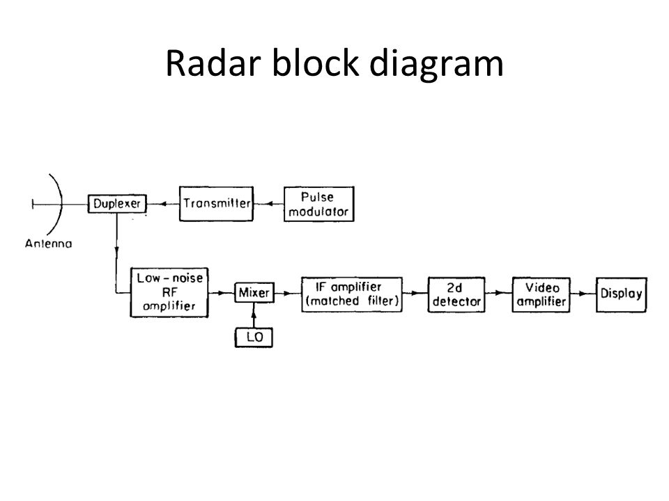
39 radar system block diagram
-Radar system block diagram. | Download Scientific Diagram Download scientific diagram | -Radar system block diagram. from publication: Drone detection and tracking based on phase-interferometric Doppler radar | Drones, Doppler and Radar | ResearchGate ... Basic Radar System Block Diagram: Fundamentals of Basic Radar ... Block diagram and description: The block diagram of Figure 16-4 shows the arrangement of a typical high-power Pulsed Radar System Block Diagram. The trigger source provides pulses for the modulator. The modulator provides rectangular voltage pulses used as the supply voltage for the output tube, switching it ON and OFF as required.
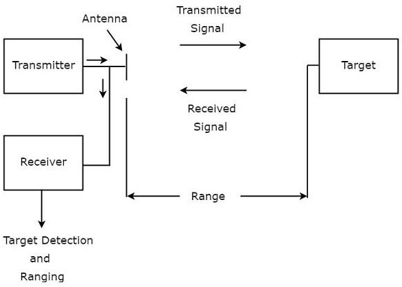
Basic block diagram of a radar system | Download ... The basic parts of a radar system are illustrated in the simple block diagram of fig.1. Radar equipment consists of a transmitter, an antenna, a receiver, and a signal processor. Radar transmitters...

Radar system block diagram
UWB Radar Tutorial | UWB Radar System working Block diagram UWB Radar system block diagram The figure depicts typical block diagram of UWB radar system. RF filter, driver, power amplifier and transmit antenna. The UWB receiver consists of receiving antenna, RF filter (BPF type), LNA (Low Noise Amplifier), down converter(using mixer and LO circuit), PDF Radar Transmitter/Receiver - MIT Lincoln Laboratory Simplified Radar Transmitter/Receiver System Block Diagram • Radar transmitter and receiver can be divided into two important subsystems - High power transmitter sections - Low power sections Radar waveform generator and receiver Duplexer Waveform Generator Receiver High Power Amplifier Filter Low Noise Amplifier A/D 00101111010 Block Diagrams for RF and Microwave Systems - Pasternack Pasternack's library RF and microwave block diagram are designed to provide engineers and designers with examples of common RF systems schematics while illustrating the RF products and where they fit into the system's design. ... Radar System. Radar Chip-Set. 13.75 - 14.5 GHz VSAT Radio. 28 - 31.5 GHz VSAT Radio. 71 - 81 GHz E-Band Radio.
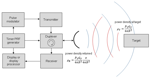
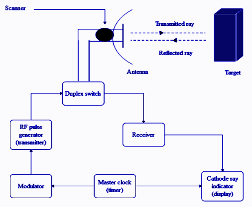
Radar system block diagram. Radartutorial Figure 1: Block diagram of an automatic frequency control in radar set Chapter: Radar Receiver Technology The function of the receiver is to take the weak echoes from the antenna system, amplify them sufficiently, detect the pulse envelope, amplify the pulses, and feed them to the indicator. Radar Working Principle - your electrical guide Block Diagram of Radar System The typical block diagram of radar system is shown in Figure. The essential elements of a radar system are: The timer device is used for coordinating the action of the transmitter, receiver, and indicator, to ensure synchronized operation. Universal Block Diagram of Pulse Radar - Radartutorial Radar Data Processor Figure 1: Universal Block Diagram of Pulse Radar This block diagram may be used for your own lessons but there are no block labels in the animation and there is no background image (landscape). These block labels can be placed in an own layer over the animation in e.g. MS-PowerPoint with text boxes in your own language version. What is radar block diagram? | Popular Answers Basic Radar System Block Diagram consists of a transmitter and a receiver, each connected to a directional antenna. The receiver collects as much energy as possible from the echoes reflected in its direction by the target and then processes and displays this information in a suitable way.
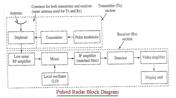
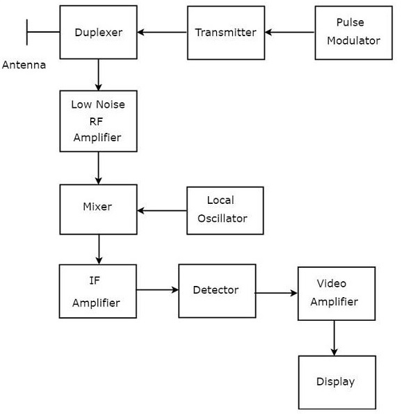
Radar Systems - Overview - Tutorialspoint RADAR is an electromagnetic based detection system that works by radiating electromagnetic waves and then studying the echo or the reflected back waves. The full form of RADAR is RA dio D etection A nd R anging. Detection refers to whether the target is present or not. The target can be stationary or movable, i.e., non-stationary. Block Diagram of Pulse Radar - Tutorialspoint Block Diagram of Pulse Radar Pulse Radar uses single Antenna for both transmitting and receiving of signals with the help of Duplexer. Following is the block diagram of Pulse Radar − Let us now see the function of each block of Pulse Radar − Pulse Modulator − It produces a pulse-modulated signal and it is applied to the Transmitter. Basic Radar Systems Basic radar block diagram. Synchronizer. The heart of the radar system is the ,synchronizer. It generates all the necessary timing pulses (triggers) that start the transmitter, indicator sweep circuits, and ranging circuits. The synchronizer may be classified as either self-synchronized or externally synchronized. In a self-synchronized system ... PDF MIT IAP 2011 Laptop Based Radar: Block Diagram, Schematics ... MIT IAP 2011 Radar Instructions-1 . GLC 8/28/2012 . MIT Lincoln Laboratory . MIT IAP 2011 Laptop Based Radar: Block Diagram, Schematics, Bill of Material, and Fabrication Instructions* Presented at the 2011 MIT Independent Activities Period (IAP) *This work is sponsored by the Department of the Air Force under Air Force Contract #FA8721-05-C-0002.
Block Diagram of Communication System with Detailed ... 23/02/2020 · Block Diagram of Communication System with Detailed Explanation. Communication By Sasmita February 23, 2020. ... computer communication, radar communication, television broadcasting, radio telemetry, radio aids to navigation, radio aids to aircraft landing etc. The Communication Process ... Electronic Warfare Digital Radar Receiver - Bradley The sub-level block diagram shown in Figure 3 displays the EW digital radar receiver in more detail than Figure 1. Block 1 mixes an analog RF signal with an analog LO frequency from Block 2 to produce an analog intermediate frequency (IF). The IF signal is sampled by Block 3 to be processed by Block 4. In addition, Block 4 controls the LO ... Radar Modulator Block Diagram - Electronics and ... Optical Fiber Communication System Block Diagram; Expression for Numerical Aperture of an Optical Fibre; Radar Display Types; Receiver Noise Figure Calculation; Radar Modulator Block Diagram; Microwave Radar Transmitters and Receivers; Delay Line Canceller Block Diagram; Moving Target Indicator Radar Block Diagram; Pulsed Radar and its ... What is Radar System? Definition, Basic Principle, Block ... Block Diagram Applications History Radar was invented for military purpose before world war II in order to secretly detect the presence of unknown objects. Initially, the transmitting tubes were not that much powerful thus worked at a very low frequency of about 60 MHz.
Basic block diagram of a radar system | Download Scientific ...
PDF Scanning Digital Radar Receiver Corporation. The objective of the system is to be able to detect a pulsed radar signal over a large frequency range. After a pulsed radar signal has been identified, the system will output the characteristics of the signal to the user. High Level Block Diagram Figure 1 is the high level system block diagram. The input, user input mode, is ...
New Facelift for Radar but the Physics Stays the Same - ADU
RADAR - Basics, Types, Working, Range Equation & Its ... Block Diagram of Pulsed Doppler RADAR Moving Target Indicator It transmits low pulse repetition frequency to avoid range ambiguities. In an MTI RADAR system, the received echo signals from the object are directed towards the mixer, where they are mixed with the signal from a stable local oscillator (STALO) to produce the IF signal.
A SFCW harmonic radar system for maritime search and rescue ...
AM3358 data sheet, product information and support | TI.com 26/10/2011 · The contains the subsystems shown in the Functional Block Diagram and a brief description of each follows: The microprocessor unit (MPU) subsystem is based on the ARM Cortex-A8 processor and the PowerVR SGX™ Graphics Accelerator subsystem provides 3D graphics acceleration to support display and gaming effects.
Lecture Notes On
Radar Block Diagram and Working Principle - Electronics and ... Sep 17, 2019 · Block Diagram of Radar: The transmitter can be a power amplifier such as klystron, travelling wave tube etc. It can also be a power oscillator such as magnetron. The radar signal is produced at low power by a waveform generator which is then amplified by the power amplifier.
RADAR Block Diagram (Bistatic RADAR & Monostatic RADAR)
Basic Radar Block Diagram - Engineering Projects May 24, 2021 · Basic Radar Block Diagram A basic radar block diagram is shown in Fig. 1. The pulse repetition frequency is controlled by the timer (also called trigger generator or synchronizer) in the modulator block. The pulse-forming circuits in the modulator are triggered by the timer and generate high-voltage pulses of rectangular shape and short duration.

Chapter 19 Weather Detection. - ppt video online download
Lecture 4: Synthetic Aperture Radar (SAR) Block Diagram Linear Rail Radar Sensor Data Acquisition and Rail Control Aircraft Models Placed on ... "Low-Cost, High Resolution X-Band Laboratory Radar System for Synthetic Aperture Radar Applications." Austin Texas: Antenna Measurement Techniques Association conference, October 2006.
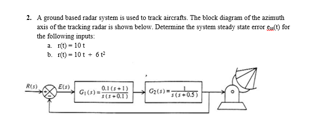
Solved 2. A ground based radar system is used to track ...
PDF Radar Fundamentals - Naval Postgraduate School Radar Block Diagram • This receiver is a superheterodyne receiver because of the intermediate frequency (IF) amplifier. (Similar to Figure 1.4 in Skolnik.) • Coherent radar uses the same local oscillator reference for transmit and receive.

Module 1.2: Radar Output Section — KB GPR Surveys
Mercedes-Benz E-Class (W212) (2009-2016) Fuse Diagram ... Valid until 28.02.2013: Weight sensing system (WSS) control unit: Valid for China, South Korea vehicles: Navigation processor: 78: Media interface control unit: 7.5: Multimedia connection unit: 79: Valid up to 31.05.2010: Radar sensors control unit: 5: Valid as of 01.06.2010: Video and radar sensor system control unit

Block diagram of the monostatic UWB microwave radar system ...
Arduino RADAR Model with Ultrasonic Sensor Servo & LCD RADAR is an object detection system that uses radio waves to identify the range, altitude, direction, and speed of the objects. The radar antenna transmits radio wave pulses that bounce off any object in its path. The object returns a portion of the wave received by the receiver which is in line of sight with the transmitter. ... Block Diagram ...
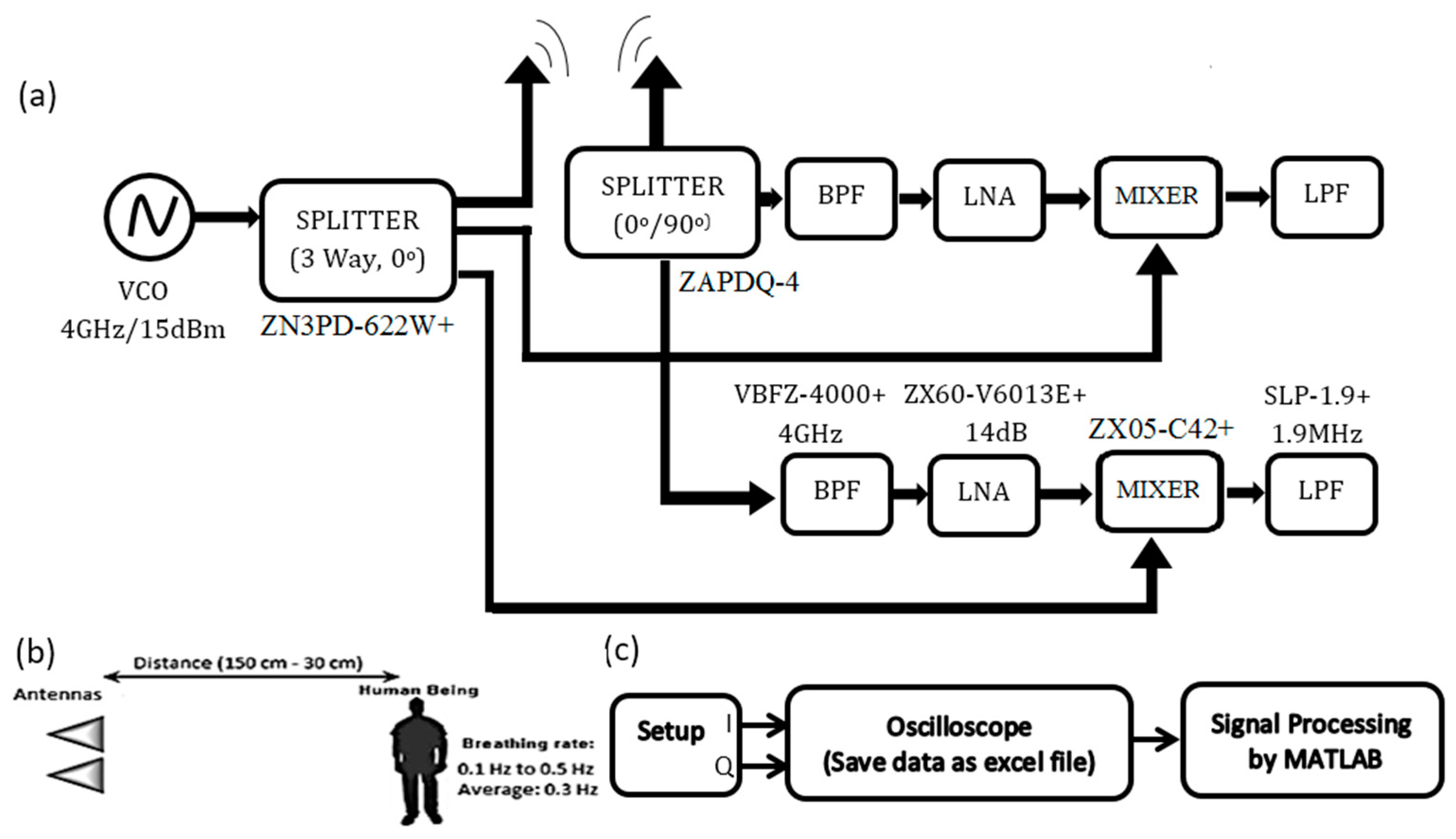
Sensors | Free Full-Text | A Doppler Radar System for Sensing ...
X-Rays | Definition Block Diagram and working of X-Ray ... Block Diagram of X-Rays machine. Figure 2: Block Diagram of X-Ray Operation/Working of X-Ray Machine High voltage source and high voltage transformer. High voltage source is responsible for providing high voltage to the H.V transformer for a decided time. The H.V transformer produces 20 KV to 200 KV at the O/P.
Explain the principle and working of RADAR with a neat class ...
Radar System - GeminiGuide.com Basic Functions of Rendezvous Radar System Diagram The radar is contained within a pressurized module. dimensions are approximately 17 by 29 by 9 inches, the module area is 1.8 cubic feet, and the weight is 72 pounds. The radar is installed in the small end of the Gemini Spacecraft on the forward face of the

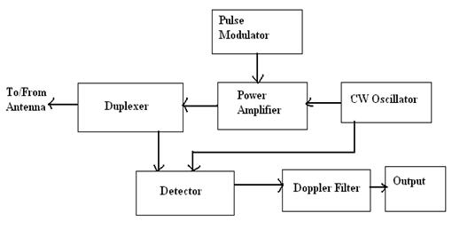
Pulsed Radar and its Comparison with CW Radar - Electronics ...
Radar system - SlideShare Fig: Block diagram of an automatic frequency control in a radar set. 24. • Few images of receiver 25. 4.DUPLEXER * DUPLEXER is an electronics switching circuit that allow time share a single antenna between the transmitter and receiver signal.

Introduction of Radar | Radar-Basics, types, working ...
Projects | Build a Small Radar System Capable of Sensing ... Radar System design slides: block diagram, schematics, bill of material, and fabrication instructions ( PDF - 4.6MB) Block diagram (high resolution image) ( JPEG) Circuit schematics (high resolution image) ( JPEG) MATLAB is presumed installed on your laptop. Some MATLAB code is supplied below for each experiment.

AP3302 - Radar Theory
Infineon’s first completely autonomous radar sensor ... 14/03/2022 · It makes it possible to use the MMIC as a ‘plug-on’ motion sensor to an existing system by connecting a power supply to voltage common collector (VCC) and ground (GND) castellated holes. The BGT60LTR11AIP is designed for low-power Doppler radar operation. The block diagram of the BGT60LTR11AIP MMIC is shown in figure 4.
Advantages of Pulsed Radar | disadvantages of Pulsed Radar
Radar Components The below figure represents a typical system for traffic radar. For multi-piece radars the antenna is usually separate from the rest of the electronics. Figure D-1 -- Radar Block Diagram Antenna GAIN Antenna gain (G) can be expressed in terms of wavelength (Lambda) and effective antenna area (A e ).

Radar Principle - Radartutorial
PDF Detection and Measurement of Radar Signals: A Tutorial SYSTEM INPUT ATTENUATION FOR RSEC MEASUREMENTS B.1 Hardline Coupling to a Radar Transmitter For hardline-coupled measurements, some attenuation will likely be required between the directional coupler output and the measurement device input (see Figure 1). Referring to this diagram, the minimum decibel amount of attenuation, A, required will be:
Basic Radar System Block Diagram: Fundamentals of Basic Radar ...
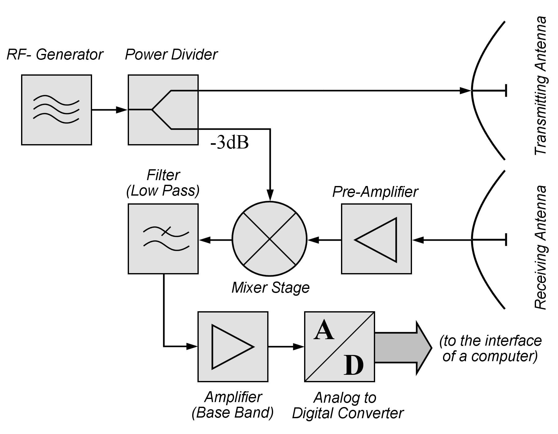
FMCW Radar System - University of Waterloo FMCW radar is less affected by the noise in comparison to impulse radars. 2.1FMCW radar basics In any radar, the electromagnetic wave is sent into the environment containing various objects. Then the echo of the wave is captured at a receiver. A simplified block diagram of such a system is shown in Fig. 1 in which both the
Radar Systems - Quick Guide
41 radar system block diagram - Diagram For You Radar system - SlideShare The radar antenna illuminate the target with a microwave signal, which is then reflected and picked up by a receiving device and Radar signals can be displayed on the traditional plan position indicator (PPI) other more advanced radar display systems Fig.2: Block diagram of a primary radar 8.
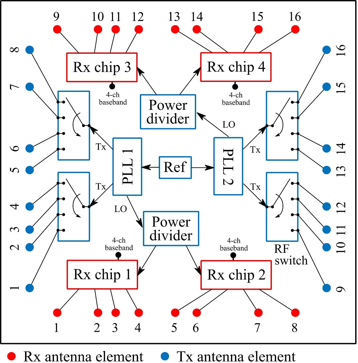
Portable 24-GHz 3D MIMO Radar – Z. PENG
Block Diagrams for RF and Microwave Systems - Pasternack Pasternack's library RF and microwave block diagram are designed to provide engineers and designers with examples of common RF systems schematics while illustrating the RF products and where they fit into the system's design. ... Radar System. Radar Chip-Set. 13.75 - 14.5 GHz VSAT Radio. 28 - 31.5 GHz VSAT Radio. 71 - 81 GHz E-Band Radio.

A Block Diagram Demonstrating a Secondary Radar | Radar ...
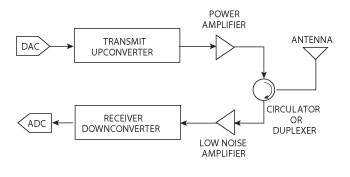
PDF Radar Transmitter/Receiver - MIT Lincoln Laboratory Simplified Radar Transmitter/Receiver System Block Diagram • Radar transmitter and receiver can be divided into two important subsystems - High power transmitter sections - Low power sections Radar waveform generator and receiver Duplexer Waveform Generator Receiver High Power Amplifier Filter Low Noise Amplifier A/D 00101111010
RADAR system References: Intoduction to Radar Systems Merill ...
UWB Radar Tutorial | UWB Radar System working Block diagram UWB Radar system block diagram The figure depicts typical block diagram of UWB radar system. RF filter, driver, power amplifier and transmit antenna. The UWB receiver consists of receiving antenna, RF filter (BPF type), LNA (Low Noise Amplifier), down converter(using mixer and LO circuit),

PIC Based Ultrasonic Radar Project
File:Bsp2 CW-Radar.EN.png - Wikimedia Commons
Radar Components
RADAR - Basics, Types, Working, Range Equation & Its Applications
Tracking Radar
ARDUINO BASED RADAR SYSTEM
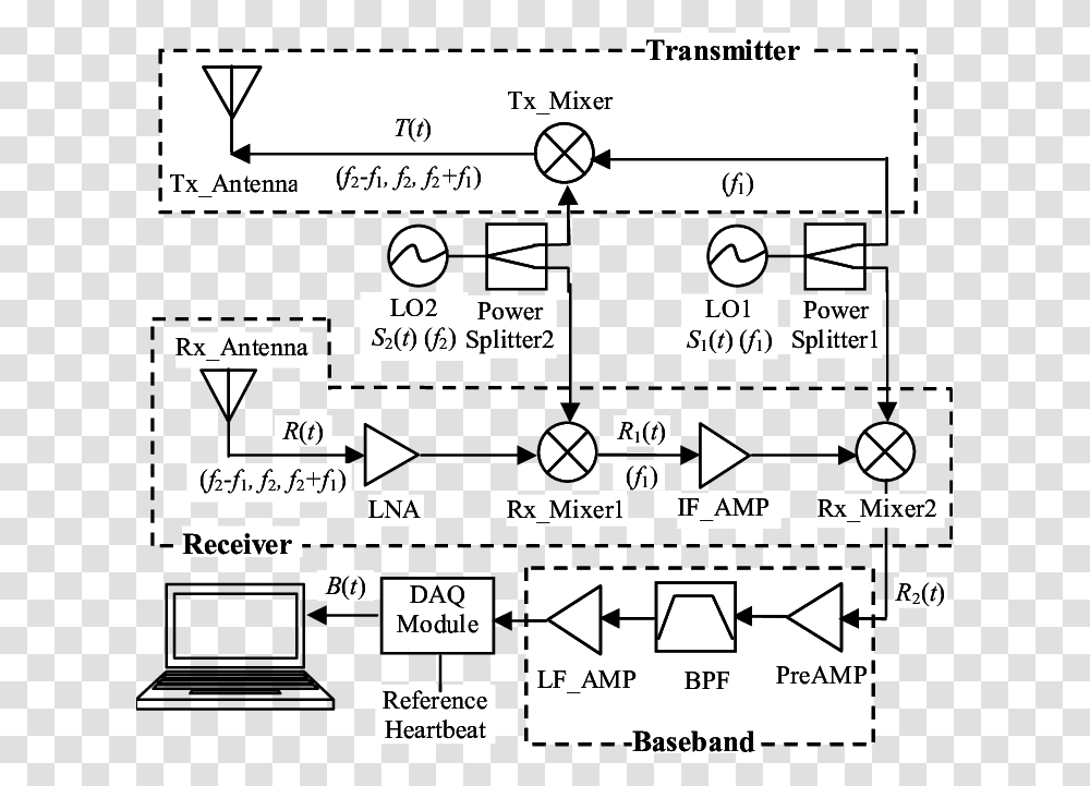
System Block Diagram Of Ka Band Heartbeat Detector Radar ...

General block diagram of the radar system. | Download ...

Waveform Design

Radar Block Diagram from Analog Devices, Inc. - Electronic ...
Radar Systems - Pulse Radar
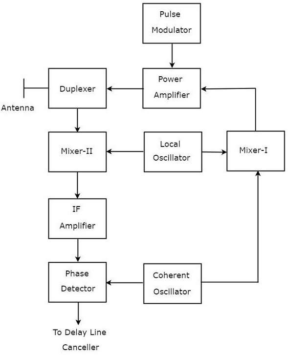
Radar Systems - MTI Radar

Explain the principle and working of RADAR with neat block ...

Working of a Pulse RADAR and its applications
Design, System Integration and Testing of Radar Systems - NI

Figure 10.1 from 0 Pulse Compression 10.1.1 Block Diagram ...

A concurrent dual-band radar sensor for vital sign tracking ...
RADAR SYSTEMS LECTURE NOTES B.TECH (IV YEAR – II SEM) (2020-21)


Comments
Post a Comment