39 joule thief circuit diagram
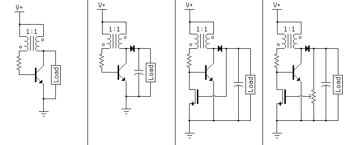
MOSFET-based Joule Thief steps up voltage - EDN MOSFET-based Joule Thief steps up voltage. A simple blocking oscillator circuit can be used to step up voltage using properties of coil inductance ( V = L di/dt ). Such a circuit is shown in Figure 1 , which is more commonly called a Joule thief. The output will be pulses of voltage that can be filtered using a diode and capacitor. › 37032009 › PHYSICS_OLYMPIADPHYSICS OLYMPIAD (ΠΗΨΣΙΧΣ ΟΛΨΜΠΙΑ∆) (ΠΗΨΣΙΧΣ ΟΛΨΜΠΙΑ∆) 1993 ... Buku kumpulan soal fisika Canada ini bakalan bikin kamu makin seneng deh sama fisika.
Joule Thief Voltage Booster Using a ... - Circuits DIY A Joule thief voltage booster is a circuit that translates a constant low voltage input into a periodic output of a higher voltage. Joule thief circuits can drain nearly all the energy from their attached power source, even if the power source is an almost dead single-cell battery.

Joule thief circuit diagram
Joule Thief Circuit - Devopedia The Joule Thief Circuit is a voltage booster circuit which converts a constant low voltage input into a periodic output of a higher voltage. This circuit can be most often seen lighting an LED with an almost dead AA battery. The peaks in voltage occur rapidly, causing the LED to flash at a very fast rate. However, the LED appears to be constantly lit to the human eye due to the persistence effect. Public circuits tagged "joule-thief" - CircuitLab Dimmable Joule Thief Buck circuit with MOSFet PUBLIC. A quick and easy circuit to control a 10v 200mA LED array using a 2N7000 MOSFET. Dimming is done through R2. by qs | updated May 09, 2013. 2n7000 buck joule-thief mosfet. 3 Best Joule Thief Circuits - Homemade Circuit Projects The radiant joule thief circuit I built From a circuit schematic featured on a youtube video and here are the results So far; With a aa size energizer battery, with a Measure voltage of only 1.029 volts left in it I got an output from the radiant Joule thief battery charger of 12.16 volts @14.7 milli amps.
Joule thief circuit diagram. Joule Thief Circuit Diagrams, Etc.... - Free Energy Joule Thief Circuit Diagrams, Etc.... « on: March 03, 2009, 06:59:52 AM ». This topic will be locked and display all of the circuits and some photos of the devices being worked on in the Joule Thief topic. This is going to take me a while to do so please be patient. 2013-06-27 When And When Not To Use A Joule Thief ... The Joule Thief or blocking oscillator circuit transfers a low voltage, high current input to a higher voltage, lower current output, with a low efficiency and high losses. It's a very simple circuit but has serious deficiencies. The typical Joule Thief's input voltage will be 1.5VDC and the output load will be one LED (or 2 or more LEDs in ... Simple Solar Circuits | Evil Mad Scientist Laboratories So, we can add to that circuit the simple Joule Thief voltage booster to get a good design for a solar garden light: A solar-charged battery with a dark detector that drives a Joule Thief to run a white output LED. Naturally, you'd want to give this a tough, weatherproof enclosure if it were going to be run outside. (A mason jar comes to mind!) 1.2v LED Flasher - Joule thief - Electronics-Lab.com This is a 1.2-volt single transistor flyback (Joule Thief) circuit that features a third coil. With it, flash duration and brightness is much enhanced, even with just a 10uF capacitor, as can be seen in the schematic. Description The parts to the right of T1 form a simple Joule-thief ('Blocking' oscillator) circuit which boosts the 1.2vRead More
vbook.pub › documents › fundamentals-of-reinforcedFundamentals Of Reinforced Concrete Design (2) [plon6n13z6w3] PROBLEM 2. 19 (CE BOARD NOVEMBE,R 2002) The continuous.reinforced concrete beam shown in Figure 05.is subjected to a uniform service dead load of 16 kN/m and a service. live load of 32 kNjm, resulting in the bending moment diagram shown. Joule Thief Circuit Diagrams, Etc.... - overunity.com Joule Thief Circuit Diagrams, Etc.... Language: To browser these website, it's necessary to store cookies on your computer. The cookies contain no personal information, they are required for program control. the storage of cookies while browsing this website, on Login and Register. ... › simplest-automatic-ledSimple Solar Garden Light Circuit - Homemade Circuit Projects Sep 12, 2021 · Instead you can try the following version which uses a joule thief circuit for boosting the 1.2 V to 3 V for the LED: If the LED doesn’t light up with a 1.5 V cell, you can try swapping the terminals of the winding between the transistor base and the 1K resistor. 34 Joule thief ideas | joule thief, joules, thief - Pinterest Jan 11, 2021 - Explore Lon Beers's board "joule thief", followed by 680 people on Pinterest. See more ideas about joule thief, joules, thief.
Joule thief - Wikipedia A joule thief is a minimalist self-oscillating voltage booster that is small, low-cost, and easy to build, typically used for driving small loads. This circuit is also known by other names such as joule resurrection circuit (JRC), joule ringer, blocking oscillator, vampire torch, or battery vampire.It can use nearly all of the energy in a single-cell electric battery, even far below the ... YX8018 Joule Thief Solar LED Driver - Electronics-Lab.com YX8018 Joule Thief Solar LED Driver. YX8018 is a 4-pin integrated circuit for driving solar powered garden LED lights and is found on many cheap garden lights. You can buy 10x YX8018 ICs on AliExpress for around $1. You will need the following parts to build one on your own: Joule Thief Circuit How to Make and Circuit Explanation A "Joule Thief" is a simple voltage booster circuit. It can increase the voltage of a power source by changing the constant low voltage signal into a series of rapid pulses at a higher voltage. You most commonly see this kind of circuit used to power LEDs with a "dead" battery, but there are many more potential applications for a ... Welcome to nginx! UNK the , . of and in " a to was is ) ( for as on by he with 's that at from his it an were are which this also be has or : had first one their its new after but who not they have – ; her she ' two been other when there all % during into school time may years more most only over city some world would where later up such used many can state about national out known university united …
Joule Thief circuit shows 8x overunity | Free energy, Power ...
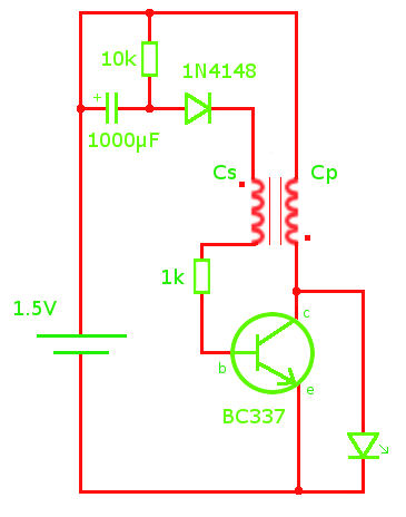
Joule Thief - All About Circuits Most Joule Thief circuit schematic specify the use of 1 or 2 coil. Question 1 - Instead of using a transformer or winding a toroid coil. Is it possible to use ready made inductor, those that look like surface mount resistor. Question 2 - Is the 1N4148 diode neccessary in the above schematic ?
Joule Thief Information Page
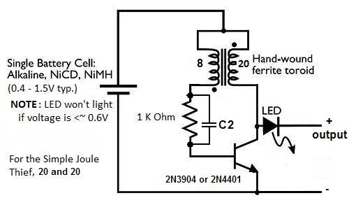
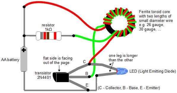
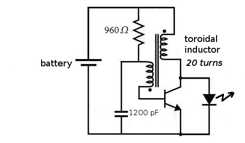
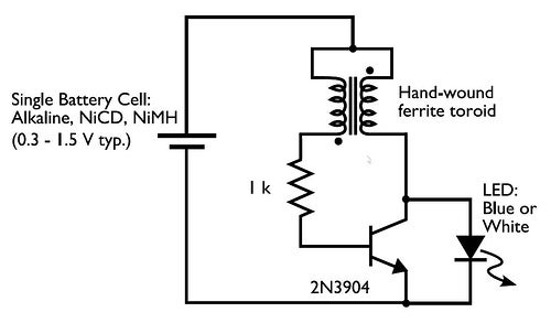
Weekend Projects with Bre Pettis: Make a Joule Thief ... In the circuit diagram for the Joule Thief, the common point of the toroid is the connection at the top of the hand-wound ferrite toroid, in the upper right of the diagram. This goes to the positive end of the battery. The other two wires from the toroid go to the resistor and to the intersection of the transistor with the LED.
LED | xyzio
Joule Thief Circuit Diagram | Windell Oskay of ... Windell Oskay of evilmadscientist.com created this diagram! It's time to celebrate #MyFlickrYear! Check your email or visit the Flickr blog for more information to ... Joule Thief Circuit Diagram. Windell Oskay of evilmadscientist.com created this diagram! Done. Comment. 26,055 views. 4 faves. 0 comments. Uploaded on November 2, 2007
File:Joule thief.png - Wikimedia Commons
How About Really Draining Dead Batteries? 1.5v to 1.2v ... How About Really Draining Dead Batteries?1.5v to 1.2v Battery Operated Circuit,DIY Joule ThiefCircuit Diagram of My Every Projects will be displayed during t...
3 Best Joule Thief Circuits - Homemade Circuit Projects
Joule Thief - solar garden light | All About Circuits Joule thief circuit issue: General Electronics Chat: 7: May 15, 2021: Is that circuit is a joule thief ? General Electronics Chat: 6: Aug 3, 2019: Solar Cell with Joule Thief: General Electronics Chat: 20: Jun 12, 2019: S: Powering LED filaments (needing 50-60 V) with a joule thief/solar light thing? Power Electronics: 10: Nov 12, 2017

Joule Thief Circuit How to Make and Circuit Explanation : 5 ...
The Ultimate How to on Joule Ringer & Joule Thief Circuits Published Aug 1, 2017. The Ultimate How to on Joule Ringer & Joule Thief Circuits. In this video I go over my latest success with joule ringers & Lasersaber's SJR Looper. I explain the learning curves of building one and what you should look for / avoid. Let me know what you think & your opinion.
joule thief under Repository-circuits -31392- : Next.gr
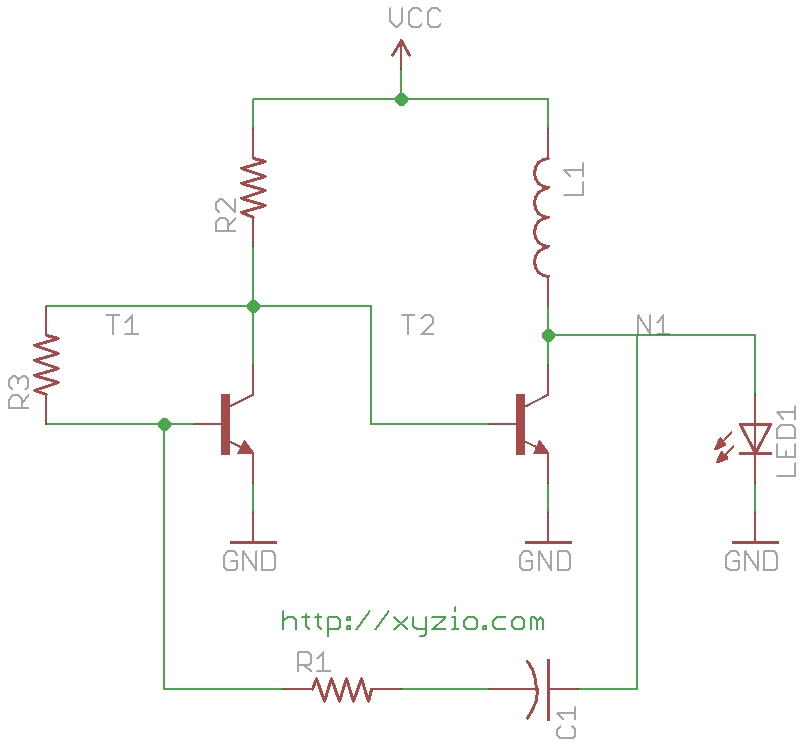
8X Overunity from Joule Thief - Homemade Circuit Projects The circuit designed by Steve can be seen in the above figure, which is a modified variant of a joule thief circuit based on "blocking oscillator" principle. In this mode, an LC network can be seen operating with the base of the BJT which you usually won't find in regular blocking oscillator designs.

Joule-Thief Circuit Performance for Electricity Energy Saving ...
Hacking an LED solar garden light - Blogs - Virtual ... The circuit pulses the small inductor to step up the voltage to drive the LED in a similar way as a Joule Thief circuit. The use of a single AAA NiCd rechargeable cell keeps the cost down. Which also means the solar panel can be a cheaper low voltage version. The 3 cm x 3 cm one from this example generated 2.7 volts in full sunlight with a ...

File:Joule thief schematic de.svg - Wikimedia Commons
"Joule Thief" Circuits, Crude to Modern... : 9 Steps ... It seems that many "Joule Thief" circuits depend on a clunky (bulky and heavy) toroid or "donut" that has to be carefully wound with copper wire. But now there are several very small 4 legged ICs available that do the job using only a simple inductor, single cell battery and a LED. In effect, the 4 legged IC replaces the clunky toroid.
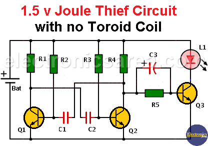
1.5 v Joule Thief Circuit with no Toroid Coil - Electronics Area
Lab 9: Sets in the Java Collection Framework ... - Course Hero Lab 9: Sets in the Java Collection Framework. For this week's lab, you will use two of the classes in the Java Collection Framework: HashSet and TreeSet.You will use these classes to …
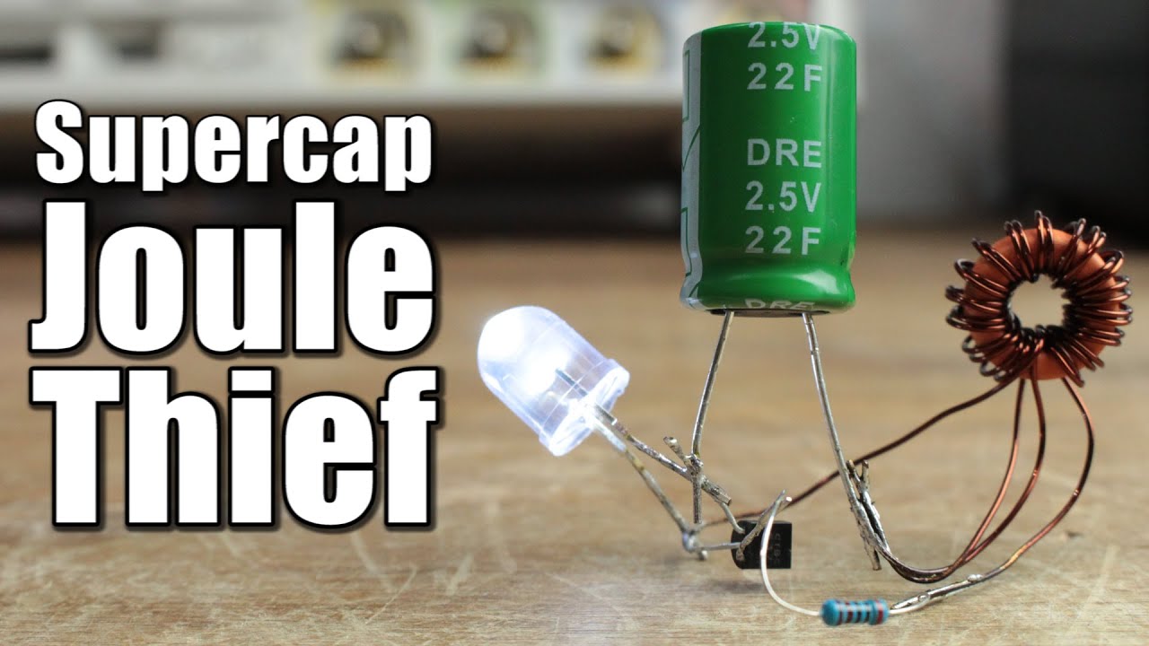
Supercapacitor Joule Thief
› ads1115ADS1115: A Low Cost 16bit ADC with Incredible Accuracy This is a similar idea to a joule thief circuit where a burst of energy stored in an inductor pulses an LED for a short time. You get enough usable light but at reduced average power. To simulate the 8SPS rate as above you would make the ADS1115 take a single shot reading every 125ms (1/125e-3 = 8) 8 Hz (you would set this repeat rate from a ...
Joule thief - Wikipedia
› how-to-make-simpleHow to Make Simple Boost Converter Circuits - Homemade ... Aug 03, 2021 · The circuit works using a joule thief concept and utilizes an inductor in the flyback mode for generating the specified high efficiency output. Using a flyback concepts allows the two side of the transformer isolated and ensures better efficiency, since the load is able to operate during the OFF time of the BJT, which in turn prevents the BJT ...
Simplifier - Voltage-Regulated Joule Thief
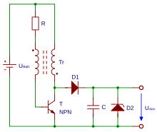
Joule thief circuit diagram - Armstrong'sblog A joule thief is a voltage booster circuit typically used for driving small loads. It can also be called a blocking oscillator. As the name implies, it can use all the energy in a single cell even when other circuits "consider" the battery "dead". This implies that it can still be supplying energy from the cell to drive a load even when ...
Joule Thief Timer - CircuitLab
What's a schematic diagram for the world's best ... - Quora Answer (1 of 2): I would suggest FET based Joule Thief. This one is declared to self-start from as low as 25 mV and lights the LED from just the heat of human hand ...
PROJECTS
puzzles.mit.edu › 2016 › puzzleThe World's Longest Diagramless - MIT The World's Longest Diagramless Everything's bigger in Texas. In this diagramless crossword, Acrosses and downs have been merged into a single combined clue list in order of appearance.
Joule Thief Circuit Diagram – DIY Electronics Projects
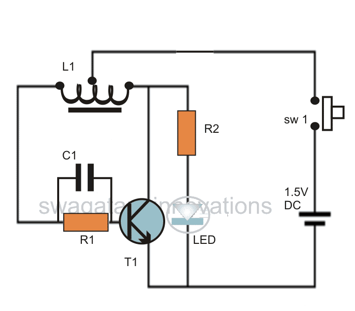
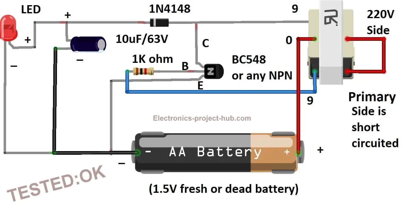
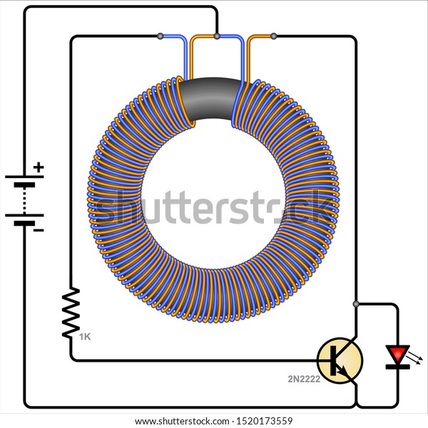
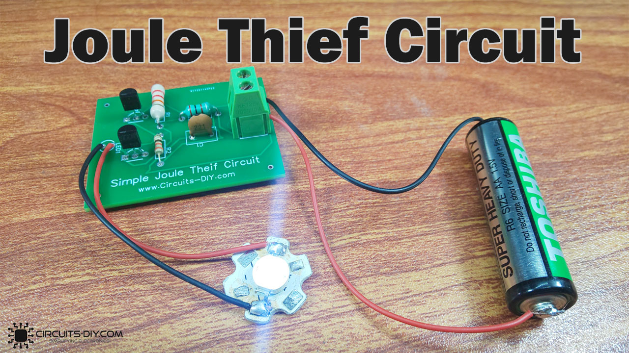
How to make a Joule Thief Circuit - circuits-diy.com This Joule Thief Circuit works by the 1.5V battery cells. When you apply the supple, current passes through the wire's coil, and a magnetic field gets generated around that coil. Consequently, it generates a greater amount of electricity in the coil. This triggers the base of transistor Q2 and hence also opens the collector-emitter channel.
Center-Tapped Joule Thief Plus
FREE PORN VIDEOS - PORNDROIDS.COM All the Free Porn you want is here! - Porn videos every single hour - The coolest SEX XXX Porn Tube, Sex and Free Porn Movies - YOUR PORN HOUSE - PORNDROIDS.COM

Joule Thief Circuit
› document › 275395703Bansal CLasses Physics Notes For IIT JEE | PDF - Scribd The maximum charge they can store individuall y in the combination is (A) 160 pC (B) 200 p,C (C) 1280 p,C (D) none ofthese y Q.31 # In the circuit shown infigure,th e ratio ofcharges on 5pF and 4pF capacitor is: ( A) 4/5 (B)3/5 (C) 3/8 (D) 1/2 3 jiF JL 5(iF 4nF 6V Q.32 In the circuit shown, a potential difference of 60V is applied across AB.

Super Efficient Joule Thief DIY - Instructables
PDF Making a Joule Thief; step-by step Making a Joule Thief; step-by step This is what the final circuit will look like... A joule thief is a circuit that allows you to use the energy (the joules) still left inside a battery that is 'dead'. We'll describe how it works after you've built it. The circuit diagram for a Joule Thief is shown on the right.

File:Regulated Joule Thief.png - Wikimedia Commons
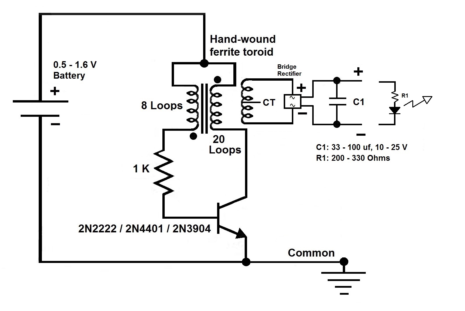
Joule Thief Circuit Diagram - DIY Electronics Projects Joule thief circuit is an oscillatory voltage booster which can boost small amount of voltage around 1V or less to a usable voltage to drive small loads like LEDs. The joule thief circuit extracts almost all energy from a standard single cell. The circuit got its name as joule thief because circuit depict like it is stealing energy from the source.
Dimmable Joule Thief Buck circuit with MOSFet - CircuitLab
Joule Thief Single Cell LED Driver - PRC68.com A blocking oscillator is a circuit that can be made into a Joule Thief by selecting parts that allow low voltage starting and is the most common circuit. Most inverter circuits will not start at low enough voltages to be called a Joule Thief.

Experiment with Joule thief circuit - Do It Easy With ScienceProg
3 Best Joule Thief Circuits - Homemade Circuit Projects The radiant joule thief circuit I built From a circuit schematic featured on a youtube video and here are the results So far; With a aa size energizer battery, with a Measure voltage of only 1.029 volts left in it I got an output from the radiant Joule thief battery charger of 12.16 volts @14.7 milli amps.

Joule Thief With Ultra Simple Control of Light Output : 6 ...
Public circuits tagged "joule-thief" - CircuitLab Dimmable Joule Thief Buck circuit with MOSFet PUBLIC. A quick and easy circuit to control a 10v 200mA LED array using a 2N7000 MOSFET. Dimming is done through R2. by qs | updated May 09, 2013. 2n7000 buck joule-thief mosfet.

Joule Thief Battery Charger: Bring Back the "Dead" - Make ...
Joule Thief Circuit - Devopedia The Joule Thief Circuit is a voltage booster circuit which converts a constant low voltage input into a periodic output of a higher voltage. This circuit can be most often seen lighting an LED with an almost dead AA battery. The peaks in voltage occur rapidly, causing the LED to flash at a very fast rate. However, the LED appears to be constantly lit to the human eye due to the persistence effect.
The joule thief flasher!

Why isnt my joule thief circuit working?the battery im using ...

Joule Thief Circuit

Joule thief - Wikipedia

Joule Thief - solar garden light | All About Circuits

Joule Thief Circuit How to Make and Circuit Explanation : 5 ...

Joule Thief
Joule Thief Circuit How to Make and Circuit Explanation : 5 ...

Tefa's electronics | Very low voltage Joule thief - voltage ...
Joule Thief Circuit Bifilar Wound Toroidal Stock Vector ...

MOSFET-based Joule Thief steps up voltage - EDN

Wind turbine Savonious Charger based on Joule Thief - advise ...
power supply circuit Page 29 :: Next.gr
Simple Joule Thief Circuit - DIY Electronics Project

Activity: DC-DC Boost Converter, For ADALM1000 [Analog ...


Comments
Post a Comment