39 electric motor brake wiring diagram
Electric Bike Wiring Diagram - Wiring Space 2018 24v36v48v 250w350w bldc motor speed controller. Electric bike wiring diagram. E Bike Controller Wiring Diagram Canopi Me For Electricbike Electric Scooter Electric Bike Kits Electric Bike . A wiring diagram is a streamlined standard photographic depiction of an electric circuit. › library › resourcesElectric Motor Power Measurement and Analysis - Yokogawa Again, note that the line-to-line voltages are 60° apart while the phase currents are 120° apart. A further detail is that if the top diagram represented a pure resistive load, then the blue currents would be in sync with the red voltages. However, with an inductive load (like a motor) the blue current vectors are out of phase with the voltages.
Leeson/Marathon Electric Brake Motors - Electric Motor ... K2044 Marathon 1 hp 3 phase 1200 RPM 145TC Frame 230/460V TEFC Marathon Electric Brake Motor. MSRP: Was: $1,732.00. Now: $1,574.90. Marathon.

Electric motor brake wiring diagram
3 Phase Motors Wiring Diagram - Wiring Diagram 2 Wire Control Circuit Diagram. Motor Control Basics. Controlling - 3 Phase Motors Wiring Diagram. Wiring Diagram includes many detailed illustrations that present the connection of assorted items. It includes guidelines and diagrams for different kinds of wiring methods along with other products like lights, windows, and so forth. 3 Phase Electric Motor Brake Wiring Diagram | Webmotor.org 3 Phase Electric Motor Brake Wiring Diagram. 3 Phase Electric Motor Brake Wiring Diagram. March 27, 2022 by masuzi. Three phase induction brake motors dc break magnetic wiring diagram show tell ac reversible motors and electromagnetic brake motor 90 watt ac. evwest.com › support › EV-Controls-T1-C-GuideEV Controls user Guide - EV West - Electric Vehicle Parts ... A JPEG image of the required circuit diagram. Diagram contains both single and dual motor circuits. High Voltage Contactor Circuit Circuit diagram of required high voltage supply circuit. Follow closely this circuit is essential to the required system circuit startup OBD 2 data connection
Electric motor brake wiring diagram. Peerless Ac Electric Motor Parts Diagram Brushless ... Peerless Ac Circuit Parts Brushless Diagram Excitation Motor System Electric Electric Motors Bearings Partsbearings 172 Diodes 1 Electric Enclosures Cabinets 0 Electric Motor Accessories 677 Electric Motor Controls 36 Electric Motor Repair Parts 514 Electric Motors 951 Gear Reducers Boxes 50 Motor Coupler Brakes Kits 5 Pumps Accessories 27 Resistance Temperature Detectors 41 Electric Motors ... 240V Motor Wiring Diagram Single Phase - Database - Wiring ... Print the wiring diagram off plus use highlighters to trace the signal. When you make use of your finger or perhaps the actual circuit with your eyes, it is easy to mistrace the circuit. 1 trick that We 2 to printing a similar wiring plan off twice. Fine Beautiful Electric Trailer Brakes Diagram 7 Pin Picture Wiring Diagram For Electric Brakes Bg Bookingritzcarlton Info Trailer Light Electricity Vw Atlas 3 Phase Motor Winding For instance if a module will be powered up and it sends out the signal of fifty percent the voltage and the technician would not know this he would think he has an issue as he would expect a new 12v signal. › vw-fault-codesVW Fault Codes DTC - Car PDF Manual, Wiring Diagram & Fault ... My car is a 1989 Chrysler lebaron turbo. Can you please send me a wiring diagram for the ignition coil to the SMEC(engine computer)? Can you also send me the wiring diagram of the pick-up coil to the SMEC? . Thank you. Email freedomfrancisxxxx13@gmail.com. Thank you #197. Francois Tabi (Monday, 21 December 2020 00:01)
Electric Brake Controller Wiring Diagram : Elecbrakes Electric Brake Controller Wiring Diagram : Elecbrakes. Electric Brake Controller Wiring Diagram. Wiring Diagram. Auxiliary connection is optional, it may be connected to any 12v to 24v constant power source or left unconnected. Break away systems may be added to the service brake circuit. Elecbrakes is designed to operate 1 to 2 braked axles. Amazing Tekonsha Trailer Brake Wiring Diagram Dc Servo Motor Tekonsha trailer brake wiring diagram. Tekonsha voyager wiring diagram. Trailers with electric brakes are required to have a breakaway system that applies the brakes in the unlikely possibility of coming loose from the. Assortment of tekonsha brake controller wiring diagram. Of the brake control a. Simplest Electric Bike Wiring Diagram - YouTube Channel Support - Website - - ... Motor Connection Diagrams - Electric Motor Warehouse Electric Motor Wire Marking & Connections. For specific Leeson Motor Connections go to their website and input the Leeson catalog # in the "review" box, you will find connection data, dimensions, name plate data, etc. Single Phase Connections: (Three Phase--see below) Single Voltage:
› opelOPEL - Car PDF Manual, Wiring Diagram & Fault Codes DTC Hello, I need a wiring diagram for Ferrari Califoria T 2014 rear camera k.markiewicz@ms-group.pl #514. Cath (Saturday, 26 March 2022 08:11) Single Phase Electric Motor Wiring Tutorial: Baldor, WEG ... In this video, Jamie shows you how to read a wiring diagram and the basics of hooking up an electric air compressor motor. These tips can be used on most ele... › suzukiSUZUKI - Motorcycles Manual PDF, Wiring Diagram & Fault Codes Mar 23, 2022 · Hi, does anyone have a wiring diagram for lexmoto assault efi 2019, the ignition switch they sell on cmpo doesn't fit to wiring loom on bike:))). They is a 6 pin plug with red, black and brown on bike and an 6 pin plug with red, black, green, black/white on ignition switch all of them in completely different positions. Guess what, bike doesn't ... Perfect Wiring Diagram For Electric Brakes Tacoma Trailer Electric trailer brake wiring schematic wiring diagram for stock trailer refrence lovely trailer wiring diagram with electric brakes wiring. Use the 7 pin connector anyway see below and just leave out the last 2 wires. It shows the components of the circuit as streamlined shapes and the power and also signal connections in between the devices ...
Motor mit Drehzahlregelung - SDG series - DKM Motor Co., Ltd ...
7 Pin Trailer Wiring Diagram With Brakes - Wirings Diagram As stated earlier, the lines in a 7 Pin Trailer Wiring Diagram With Brakes signifies wires. Sometimes, the cables will cross. But, it doesn't mean link between the cables. Injunction of two wires is usually indicated by black dot on the junction of 2 lines. There will be primary lines which are represented by L1, L2, L3, and so on.

What is Braking? Types of Braking | Regenerative Plugging ...
Dexter Electric Brakes Wiring Diagram - easywiring Dexter electric brakes wiring diagram. Use a 4mm x 2 core cable for your active and earth wires to the brakes separate from wiring used for lighting etc. This controller features a patented accelerometer design which senses the deceleration of the towing vehicle and sends a proportional voltage to the electric trailer brakes.
Wiring Information
Electric Motor Brakes - KEB Electric motor brakes are used to decelerate or hold motor loads when the power is cut intentionally or accidentally. KEB has been supplying motor brakes since our founding - this gives us more than 48 years of experience. Beyond our core brake technology, KEB is able to offer custom designs which help motor manufacturers during assembly and meet the application requirements. This post gives ...
AC Motors
Electric Motor Brake Wiring Diagram - Free Wiring Diagram Electric Motor Brake Wiring Diagram Collection of electric motor brake wiring diagram. A wiring diagram is a streamlined standard photographic representation of an electric circuit. It shows the parts of the circuit as simplified forms, and the power and signal connections between the tools.

Service and Maintenance. SEW-EURODRIVE Driving the world ...
Baldor Motor Wiring Diagram - Wirings Diagram Baldor Motor Wiring Diagram - baldor 5hp motor wiring diagram, baldor brake motor wiring diagram, baldor dc motor wiring diagram, Every electrical structure is composed of various diverse parts. Each component should be set and connected with different parts in particular way. If not, the arrangement will not function as it should be.
Item # H2L28T060-BBL4A, Brother GTR Series H2 High Torque AC ...
Hydrastar Electric Over Hydraulic Wiring Diagram - U Wiring A wiring diagram is a streamlined conventional pictorial representation of an electric circuit. If you need any wiring connectors then you can use part DW05745-10 and part DW05762-1. Hydrastar eliminates the brake drag common with surge actuators on downhill grades and also works easily in reverse.

Brake Wiring Diagram | MachMotion
Fabulous Electric Motor Wiring Connections Trailer Brakes ... Fabulous Motor Wiring Electric Connections Diagram Brakes Trailer Turn Off The Power Coming Into The Motor And Open The Cover Which Encloses The Terminals. Fabulous Motor Wiring Electric Connections Diagram Brakes Trailer Strip The Power Wire Ends And Crimp On Terminals.
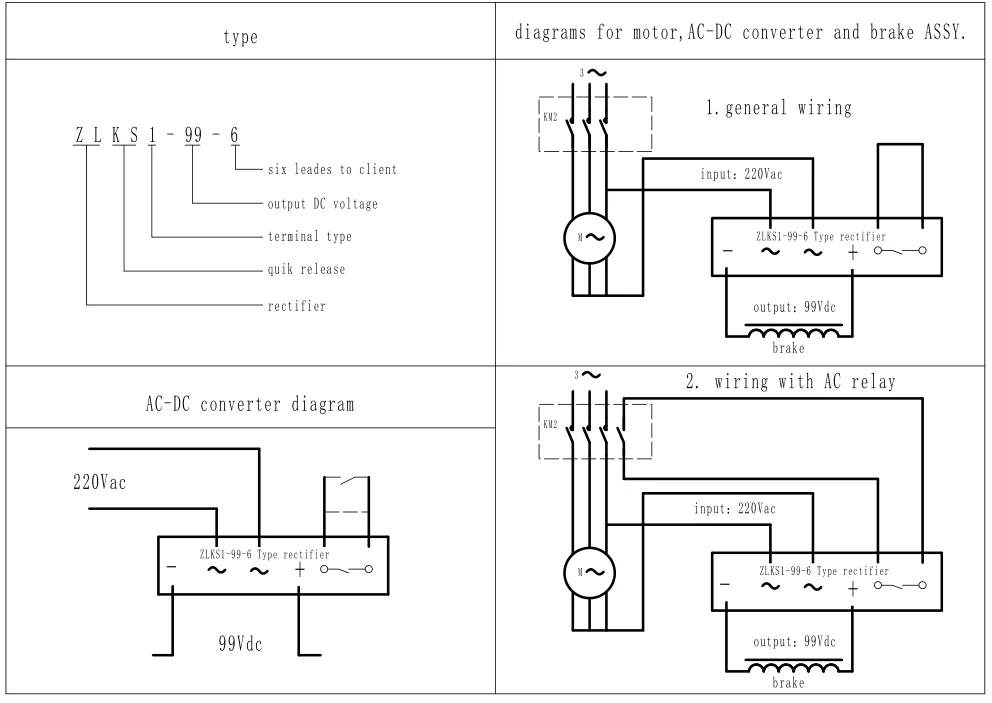
Half Wave Rectifier Zlks1-99-6 Brake Rectifier Block - Buy ...
Baldor Industrial Motor Wiring Diagram - easywiring A wiring diagram is a simple visual representation from the physical connections and physical layout associated with an electrical system or circuit. Weg motor capacitor wiring diagrams schematics and baldor diagram in. Baldor reliance industrial motor wiring diagram new wirh baldor.
Electric Brake Control Wiring
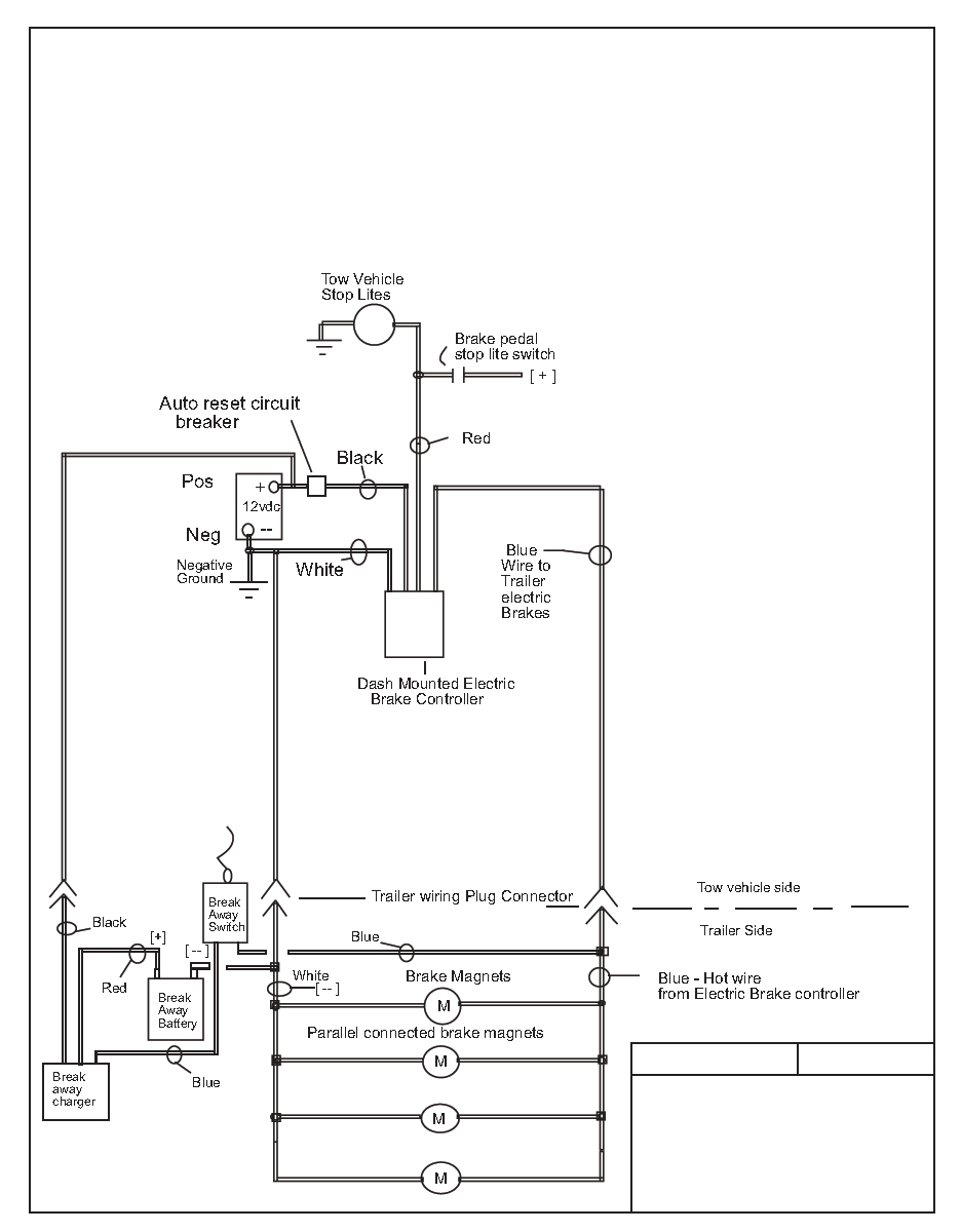
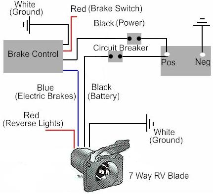
PDF Brake Control Wiring Diagram - AnythingTruck.com The BLACK wire is the power supply line to the brake control. 4. The RED (stoplight) wire must be connected to the cold side of the brake pedal stoplight switch. Splice down line from the switch; DO NOT disturb the position of the switch. 5. The BLUE (brake output) wire must be connected to the trailer connector's brake wire.
Motor Wire Drawing
PDF DR Motor Common Connection Diagrams - SEW-EURODRIVE power is applied to the motor, the brake releases (requiring no additional brake supply wiring). The brake can be wired to the motor terminal block under the following conditions: a single speed motor, the motor is started and run across the line, and the brake voltage is equal to either the low or high motor voltage.
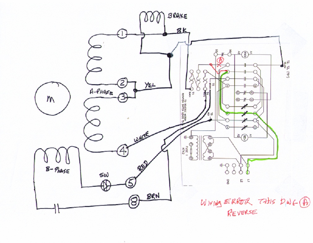
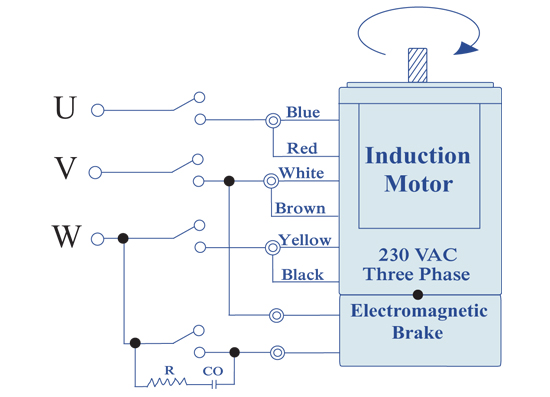
THREE PHASE INDUCTION BRAKE MOTORS
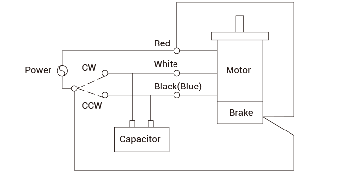
M.G.M. » Wirings diagrams - MGM Electric Motors Brake type. Brake connection. Motor connection. Diagram. Motor rated voltage. Brake rated voltage. 1. AC - 3 phases (BA(X) only) Δ/Y(6w) Δ/Y (6w) Diagram. 265V/460V/60Hz, 330V/575V/60Hz, 220V/380V/60Hz,… 265V/460V/60Hz, 330V/575V/60Hz, 220V/380V/60Hz,… 2. YY/Y(9w) Diagram. 230V/460V/60Hz,… 230V/460V/60Hz,… 3. Single phase rectified ...

Safe Torque Off (STO), motor temperature and brake wiring ...
Dayton Electric Motors Wiring Diagram Download - Wiring ... Dayton Electric Motors Wiring Diagram Download Simple Electric - Dayton Electric Motors Wiring Diagram Download. Wiring Diagram comes with a number of easy to adhere to Wiring Diagram Guidelines. It really is meant to aid all of the average person in creating a suitable system. These instructions will probably be easy to grasp and implement.
Dynamic braking for AC Induction Motor - ECN Electrical Forums
amatrol.com › coursepage › electric-motors-trainingAC Electric Motor Control Systems Training | Amatrol The 85-MT5’s industrial electric and AC motor training curriculum is unmatched within the industry for its breadth and depth of motor control topics and hands-on skills. This curriculum advances through topics like three-wire start/stop control, reversing magnetic motor starter, and on-delay and off-delay timers that can then be used to ...

Practical Machinist - Largest Manufacturing Technology Forum ...
Electric Brake Controller Wiring Diagram - The Wiring A wiring diagram is a streamlined conventional pictorial representation of an electric circuit. Electric Brake Controller Wiring Diagram. 6 and 7 Way Plugs Wiring Diagram Boat trailer lights With the power sorted (but not connected to the battery) three more tails in the wiring loom need connecting. Electric brake controller wiring diagram.

Induction Motor Braking-Plugging, dynamic, regenerative
› hoist-troubleshootingHoist Troubleshooting | Common Problems - Hoists Direct Electric hoist hook moves in wrong direction. Possible Cause: (i) Wiring connections reversed at either the control station or terminal board. (ii) Failure of the motor reversing switch to effect dynamic braking at time of reversal. (iii) Phase reversal (three phase unit only). Possible Solution: (i) Check connections with the wiring diagram.
Electromagnetic Brake Motor 90 watt, Manufacturer, Pune, India
Electric Motor Brake Wiring Diagram - Database - Wiring ... Electric Motor Brake Wiring Diagram. Electric Motor Brake Wiring Diagram from i.pinimg.com. Print the wiring diagram off plus use highlighters to trace the signal. When you make use of your finger or perhaps the actual circuit with your eyes, it is easy to mistrace the circuit. 1 trick that We 2 to printing a similar wiring plan off twice.

motor - Electromagnetic Brake Control Circuit - Electrical ...
3 Phase Wiring for Dummies - Understanding Motor ... How to Wire a Three Phase Motor. A three-phase motor must be wired based on the diagram on the faceplate. The first step is to figure out the voltage of your phases. In the United States, for low voltage motors (below 600v), you can expect either 230v or 460v. That being said, there is a wide range of different motors and what you have on hand ...
10-3856-00 Electric Motors General Wiring Instructions DANGER
Servo Motor Circuit Diagram - U Wiring A wiring diagram is a type of schematic. This pulsing signal tells the servo motor when to start rotating and which way to rotate. Ad Experienced repair service since 1985. This circuit is designed to give PWM Pulse Width Modulation signal output by using this different duty cycle PWM pulse we can control the servo motor rotation and position.
THREE PHASE INDUCTION BRAKE MOTORS
evwest.com › support › EV-Controls-T1-C-GuideEV Controls user Guide - EV West - Electric Vehicle Parts ... A JPEG image of the required circuit diagram. Diagram contains both single and dual motor circuits. High Voltage Contactor Circuit Circuit diagram of required high voltage supply circuit. Follow closely this circuit is essential to the required system circuit startup OBD 2 data connection
Three-phase motor braking circuit 2 - Basic_Circuit - Circuit ...
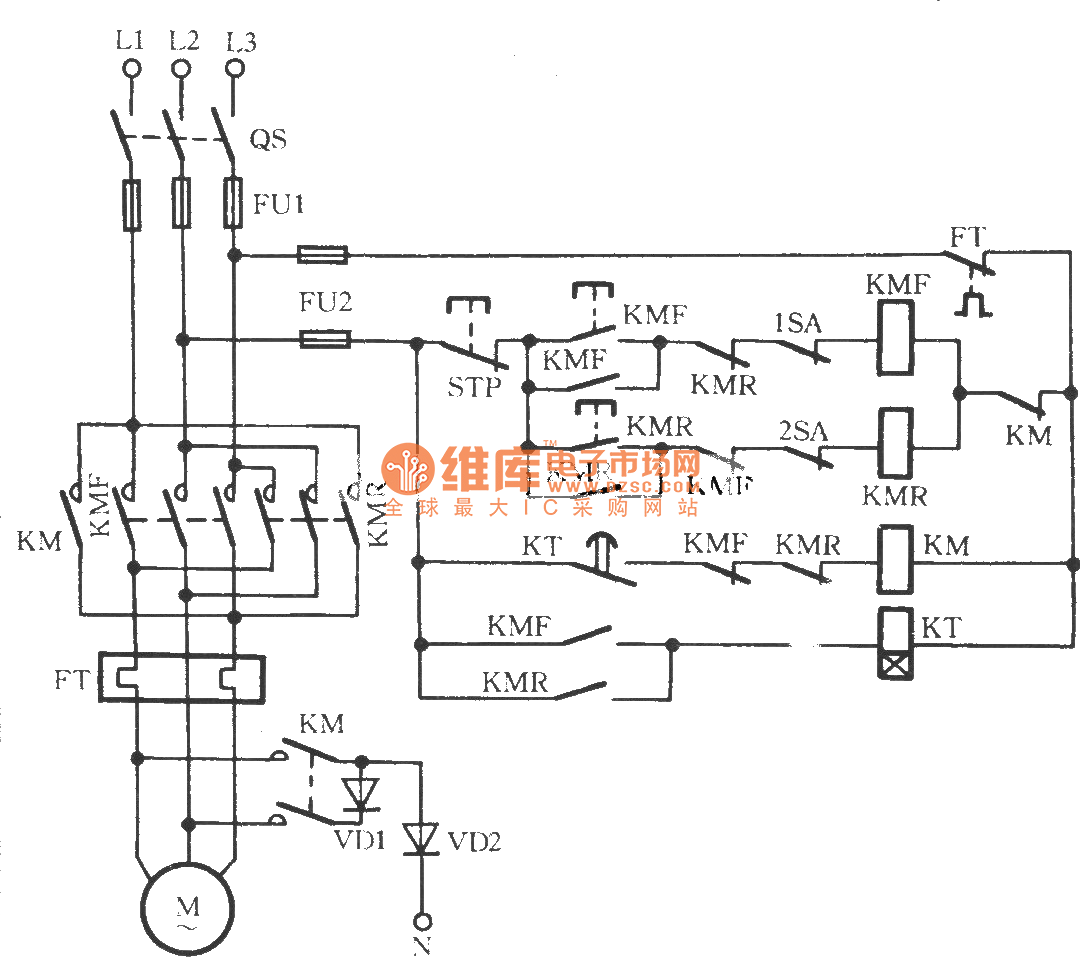
3 Phase Electric Motor Brake Wiring Diagram | Webmotor.org 3 Phase Electric Motor Brake Wiring Diagram. 3 Phase Electric Motor Brake Wiring Diagram. March 27, 2022 by masuzi. Three phase induction brake motors dc break magnetic wiring diagram show tell ac reversible motors and electromagnetic brake motor 90 watt ac.
Support and Application Data/Wiring Diagrams for our products
3 Phase Motors Wiring Diagram - Wiring Diagram 2 Wire Control Circuit Diagram. Motor Control Basics. Controlling - 3 Phase Motors Wiring Diagram. Wiring Diagram includes many detailed illustrations that present the connection of assorted items. It includes guidelines and diagrams for different kinds of wiring methods along with other products like lights, windows, and so forth.
Wiring a 2 pole three-phase DB motor to a VFD - Electrical ...

Industrial Motor Control: Braking
Electromagnetic Brake Motor 25 watt, Manufacturer, Pune, India
dc motor - Regenerative Braking circuit - Electrical ...
How to wire a DC Injection Brake on a 3-Phase motor | The ...

25 watt Electromagnetic Brake Motor And Gear Motor | Swipfe ...
New DC Motor Speed Control with Dynamic Braking - Bodine ...
Handbook of Electric Machines
How To Install A Electric Trailer Brake Controller On A Tow ...

Wiring Diagrams - Electrolift
Brake rectifier, GHE40L

Top 7 Use Cases for Electric Vehicle Simulation - MATLAB ...
AC Motors, Brake Motors DR/DV/DT/DTE/DVE, Asynchronous ...
AC Motors, Brake Motors DR/DV/DT/DTE/DVE, Asynchronous ...

Buy ZXTDR Full Set of 48V 1800W Brushless Electric Motor ...

72v Wiring Diagram | Electrical diagram, Scooter, Electric ...

DC Motor Braking Circuit Diagram | Elec Eng World | Circuit ...

Motor and shunt braking resistor - Triton


Comments
Post a Comment