43 vacuum hose routing diagram
01.05.1997 · Once the vacuum is there, the weight of the air, or atmospheric pressure, pushes the water up the straw. Consequently, the height that you can lift the water with a … The kitchen sink will connect to that same 3-inch pipe, and that pipe will then pick up the tub before it hits the combo wye in the diagram. Plus, the bathroom sink is already vented separately (probably into the attic, but that's another project), so I think I should be good.
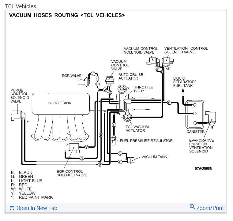
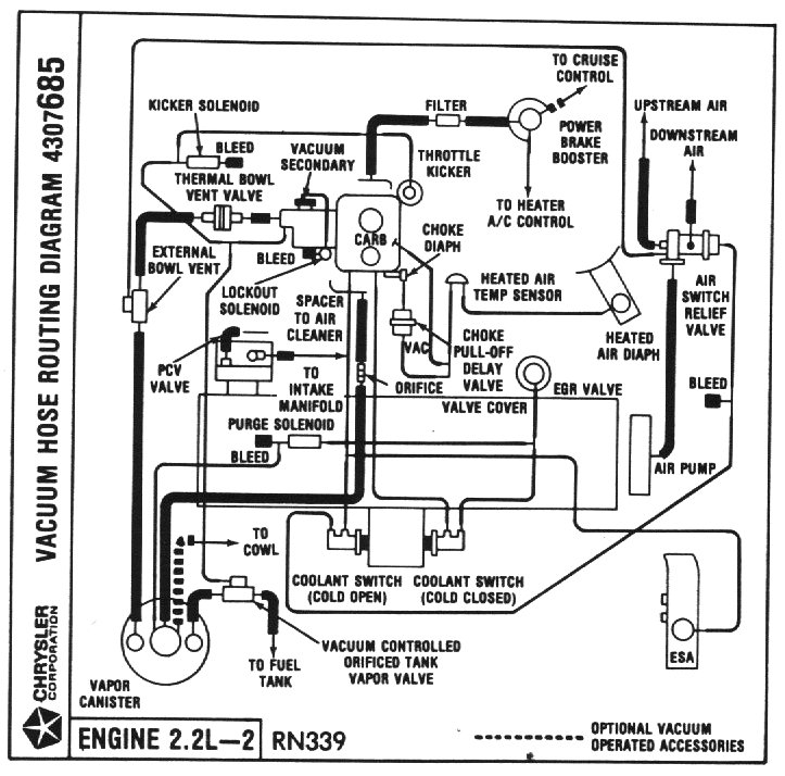
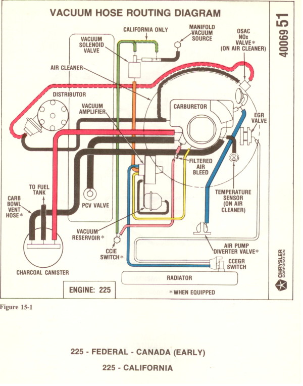
Jan 06, 2022 · The vacuum diagram shows the different vacuum controlled devices and how they interconnect. Newer vehicle models depict the components resemblance and their location. OK. Now that you have the vacuum diagram for your vehicle, you can start troubleshooting for a potential vacuum leak.
Vacuum hose routing diagram
PERIODIC MAINTENANCE 2-10 FUEL HOSE Inspect Interval Inspect Initial 1,000 km and Every 6,000 km, Replace every 4 years. Remove the seat. (Refer to page 7-1) Remove the fuel tank. (Refer to page 4-1) Remove the frame cover. (Refer to page 7-2) Inspect the fuel hoses for damage and fuel leakage. Page 26 2-11 PERIODIC MAINTENANCE FOOTREST POSITION … Jun 23, 2015 · Refer to the drive belt routing diagram located on the radiator shroud. Step 10 – Connect the pressure hoses and Tee fitting. Ensure that the O-rings on the hard lines are not worn out. Use a high pressure hose to connect the Hydroboost unit to the gearbox. Thread the hard line of the hose into the driver's side of the Hydroboost unit. Scout II, Traveler & Travelall vacuum hose routing 83kb. Air conditioning wiring diagram 16kb. V-8 wiring diagram (AT with electronic ignition) 20kb. Front light wiring harness diagram 19kb. Gauges wiring and circuits 31kb. Dome & courtesy lights wiring diagram 17kb . Parking brake indicator wiring 16kb. Rear wiring harness 19kb. Trailer lighting connections 15kb. …
Vacuum hose routing diagram. Sep 14, 2012 · 15: A vacuum diagram is supplied with each kit but we also suggest using your shop manual for proper routing and color identifications. If you do not have a shop manual, you can purchase one from Zip Products. Below are vacuum line diagrams for the mk4 ALH (below left) and BEW (labeled BEW) engines. (1Z and AHU engine vacuum diagram was in the ecu hose article linked above). There should be stickers above the radiator support that have vacuum diagrams there too if you don't have one of these engines. 2. Bad/sticking VNT actuator or turbo vanes First , find the problem area on the Vacuum diagram. Highlight the individual area. Trace the Vacuum till you can see where a problem may have taken place. Eliminate each portion of the diagram in sections until you find the leak in the Vacuum. This makes knowing where to check connections easy with an automotive Vacuum diagram. Please be specific on what area of … Mar 06, 2004 · Here is another set of scanned pages outlining the vacuum routing for mid-1970’s Jeep engines. Here is a poor-quality scan of the V8 vacuum diagram from a 1984-85 FSJ manual. Here are two more poor-quality scans of the V8 vacuum diagram from a 1989 V8 Grand Wagoneer with heavy duty and light duty cooling packages.
8-16 SERVICING INFORMATION OIL RETURN TANK HOSE ROUTING 1 Face the tip of clip to the front 2 Face the tip of clip to the bottom... Page 241: Cooling System Hose Routing SERVICING INFORMATION 8-17 COOLING SYSTEM HOSE ROUTING... Page 242: Front Brake Hose Routing 8-18 SERVICING INFORMATION FRONT BRAKE HOSE ROUTING REAR BRAKE HOSE ROUTING... 07.03.2010 · Vacuum Hose Routing Diagram (1990 5.0L V8 F150, F250) Vacuum Hose Routing Diagram (1991 5.0L V8 F150, F250) What Does The Oxygen Sensor Do? (Ford F150, F250, F350) What Does The MAF Sensor Do? (Ford F150, F250, F350) Scout II, Traveler & Travelall vacuum hose routing 83kb. Air conditioning wiring diagram 16kb. V-8 wiring diagram (AT with electronic ignition) 20kb. Front light wiring harness diagram 19kb. Gauges wiring and circuits 31kb. Dome & courtesy lights wiring diagram 17kb . Parking brake indicator wiring 16kb. Rear wiring harness 19kb. Trailer lighting connections 15kb. … Jun 23, 2015 · Refer to the drive belt routing diagram located on the radiator shroud. Step 10 – Connect the pressure hoses and Tee fitting. Ensure that the O-rings on the hard lines are not worn out. Use a high pressure hose to connect the Hydroboost unit to the gearbox. Thread the hard line of the hose into the driver's side of the Hydroboost unit.
PERIODIC MAINTENANCE 2-10 FUEL HOSE Inspect Interval Inspect Initial 1,000 km and Every 6,000 km, Replace every 4 years. Remove the seat. (Refer to page 7-1) Remove the fuel tank. (Refer to page 4-1) Remove the frame cover. (Refer to page 7-2) Inspect the fuel hoses for damage and fuel leakage. Page 26 2-11 PERIODIC MAINTENANCE FOOTREST POSITION …
Vacuum Hose Routing Gen 1 Info. | Maintenance and Do-It ...

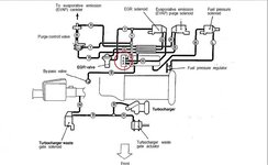
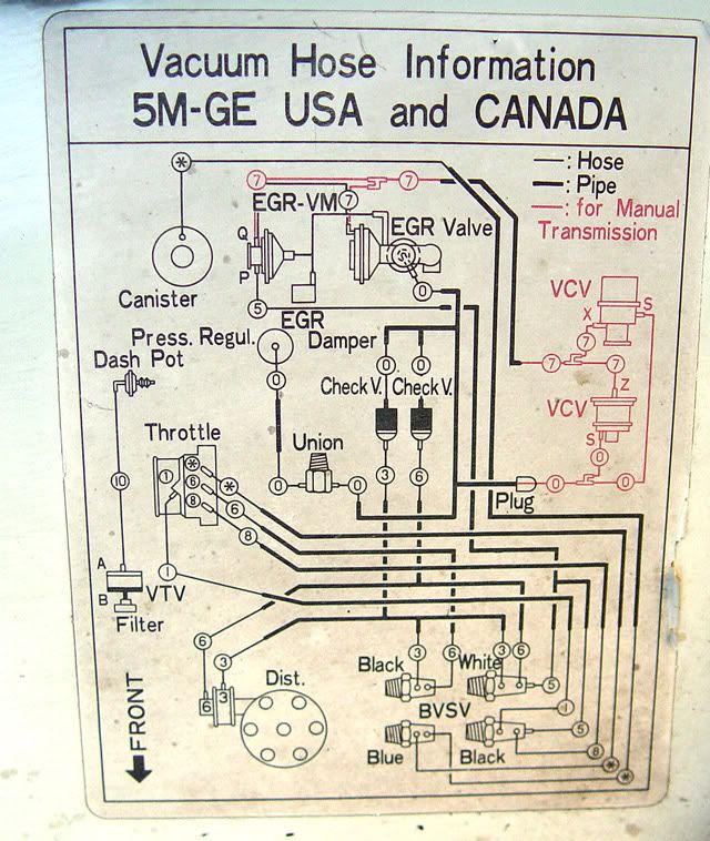
VACUUM HOSE PIPING DIAGRAM
Vacuum Hose Routing Diagram Needed Please: I Recently Did a ...
![VACUUM (Diagrams) - [PDF Document]](https://reader020.staticloud.net/reader020/html5/20190806/55cf9d9b550346d033ae5d02/bg4.png)
VACUUM (Diagrams) - [PDF Document]

Can i get a diagram on the vacuum hose routing connection for ...
Vacuum hose routing? | GalantVR4.org
Vacuum house routing diagram
How to Find and Fix a Vacuum Leak - AxleAddict
Vacuum line routing - EvolutionM - Mitsubishi Lancer and ...

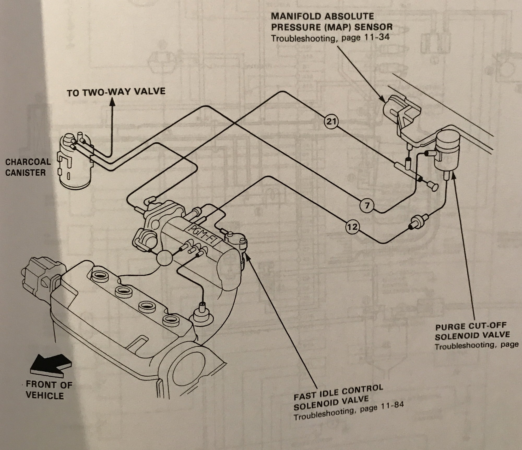
90-91 Integra B18A1 Vacuum Diagram (with dashpot valve) – HA ...
Printing from undefined
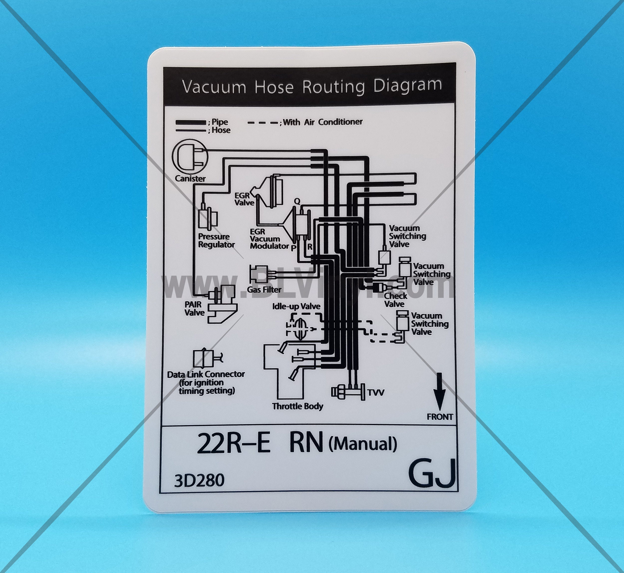
Mid-90s 22RE Vacuum Hose Routing Diagram (1994, Manual)
Vacuum Hose Routing Diagram | IH8MUD Forum
Vacuum Hose Routing/Diagram | DSMtuners.com

Vacuum Diagrams PDF | PDF
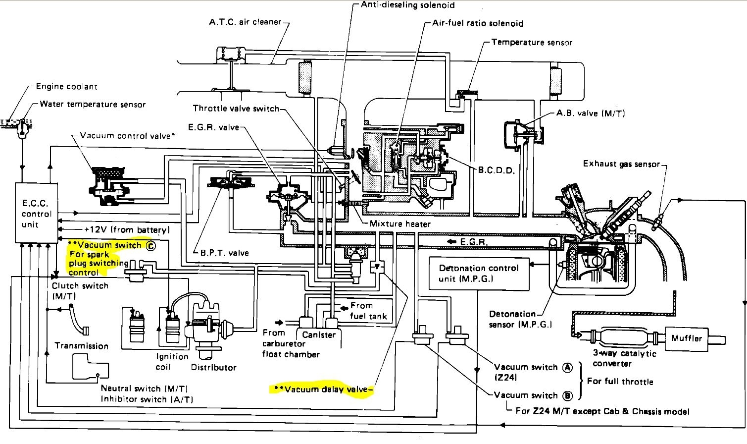
Vacuum Line Routing Diagram: Truck Listed Above Is a 720, Z24 ...
Fuel and vacuum line routing | Kawasaki VN750 Forum

Can I get a copy of the vacuum system routing diagram for a ...

VACUUM HOSE PIPING DIAGRAM
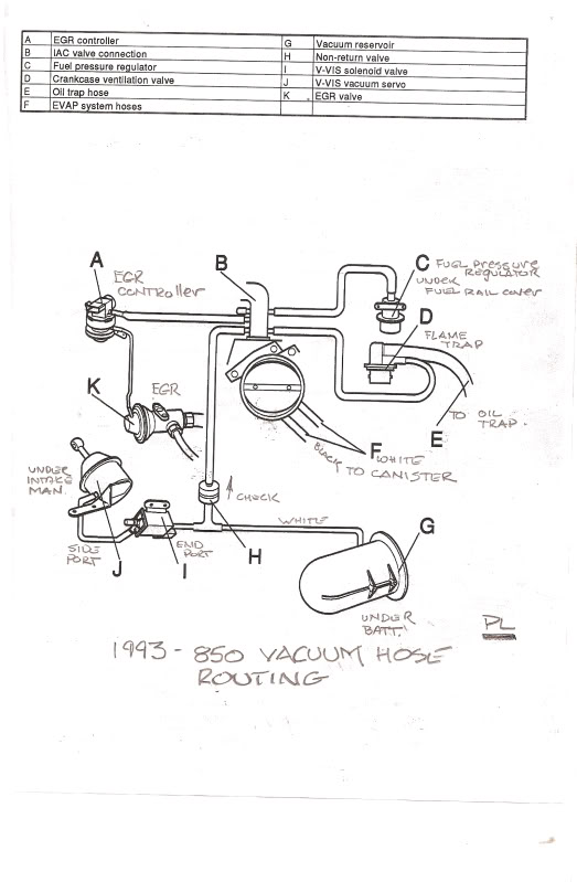
Volvo 850 vacuum diagrams | Volvotips

vacuum hose routing diagram | Diagram, Vacuum, Hose

Honda OEM Diagram Vacuum Hose Routing

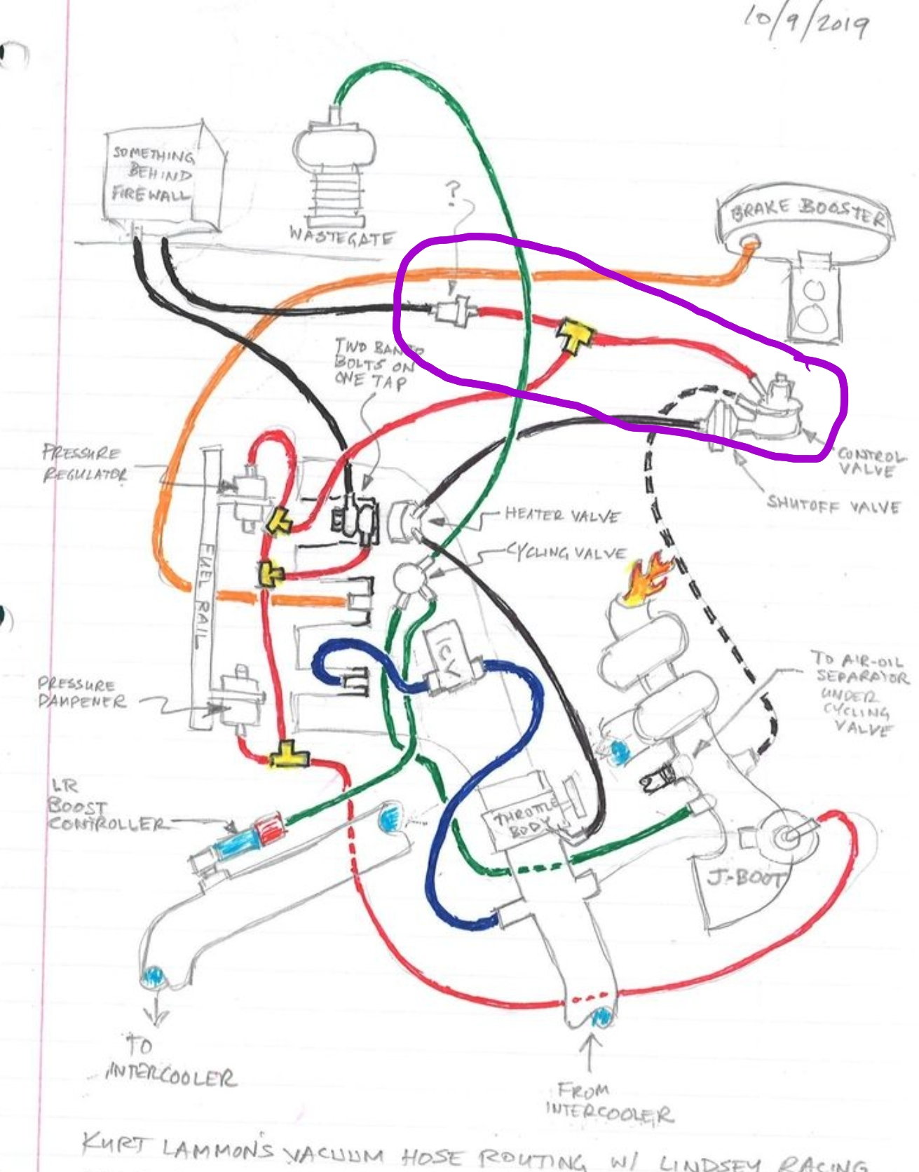
Run away screaming: 1985 Honda CVCC vacuum hose routing diagram
Vacuum Hose Routing Diagrams - MiniMopar Resources

FINALLY, a Vacuum Hose Diagram - Page 3

Vacuum Hose Routing Diagram | Infiniti G20 Nissan Primera Forum
Need a 94 850 NA vacuum diagram - Volvo Forums - Volvo ...
Vacuum Line Problems | Toyota Celica Supra Forum
Routing Vacuum Lines - Honda-Tech - Honda Forum Discussion
Mopar Truck Parts :: Dodge Truck Technical Information

Honda OEM Diagram Vacuum Hose Routing

External Wastegate Vacuum Line Routing Question - Performance ...

fragile hard vacuum lines - a hard luck story - Third ...

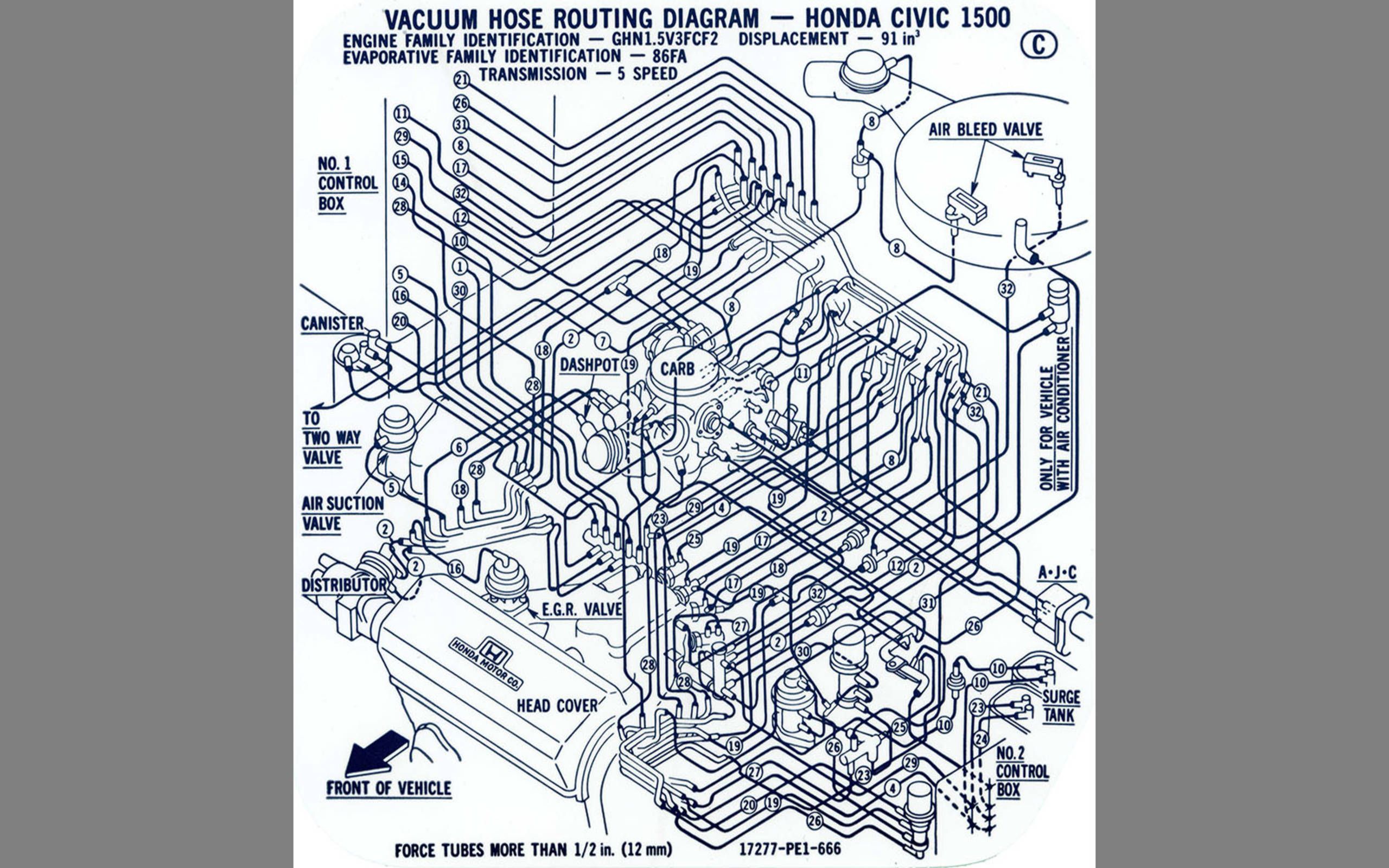
Vacuum Hose Routing Diagram -- Honda Civic 1500 - Album on Imgur
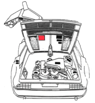
Vacuum Hose Routing | DeLorean Tech Wiki | Fandom
milleniatech.net - KL-ZEM (2.3L V6) Vacuum Hose Routing ...
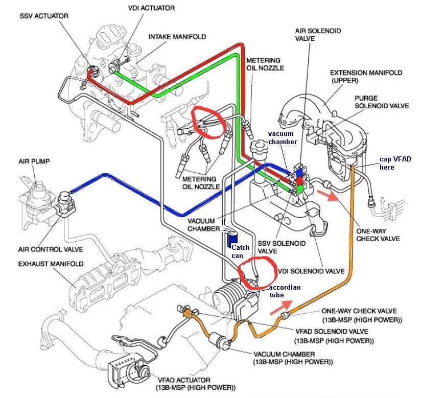
Vacuum hose diagram - RX8Club.com
Vacuum line diagram questions - Rennlist - Porsche Discussion ...

Tune-up, Vacuum Hose Routing Sticker -Under Hood-Needed ...
Run away screaming: 1985 Honda CVCC vacuum hose routing diagram
Vacuum hose routing | Suzuki GSX-R Motorcycle Forums Gixxer.com
Vacuum hose routing - Camry Forums - Toyota Camry Forum
Nissan 720 Pickup Truck Vacuum Hose Routing and Repair Guide


Comments
Post a Comment