42 ford external voltage regulator wiring diagram
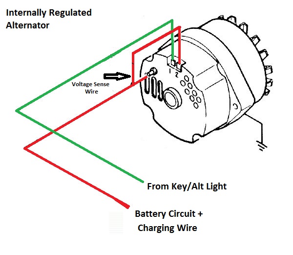
Ford Alternator Wiring Diagram Internal Regulator - ford alternator wiring diagram internal regulator, Every electrical arrangement is made up of various diverse parts. Each part ought to be set and connected with different parts in specific manner. If not, the structure will not work as it ought to be. About Regulator Wiring Voltage Diagram External . Replacing the Voltage Regulator I just did this as part of my 04 Aero Wagon's mid-life refresh. Replaces GM #2977373, #12117384, #89057722 and AC-Delco #PT516. This signal is connected to Port D, bit 13.
Oct 23, 2012. #2. It all works by F.M. Actually the voltage regulator doesn't "sense" a idiot light. The light is grounded through the case of the alternator when it isn't making voltage, thus completing the circuit and turning the light on. When the alternator is creating voltage, it sends POWER back to the bulb on that ground wire so there is ...
Ford external voltage regulator wiring diagram
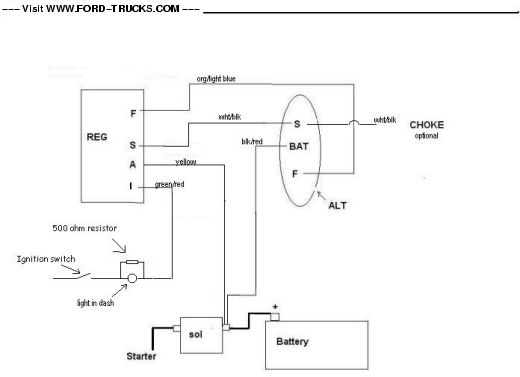
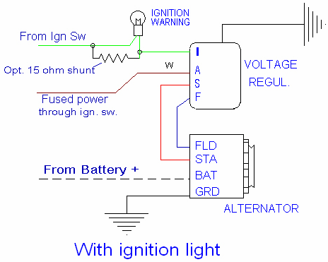
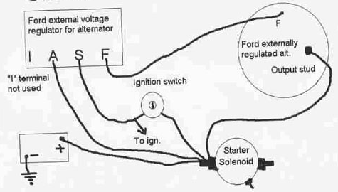
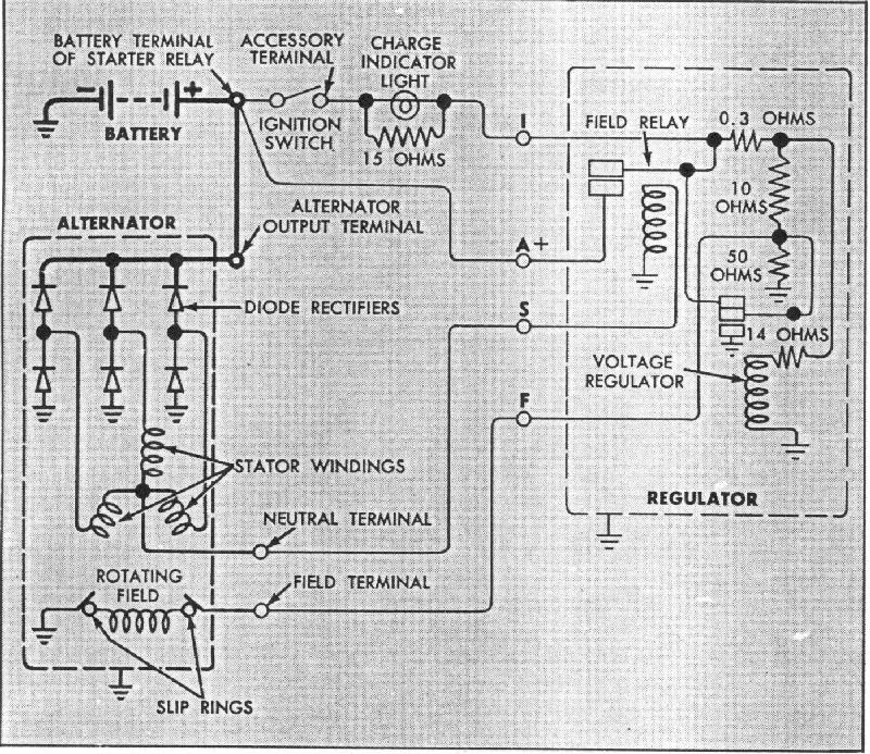
Search: External Voltage Regulator Wiring Diagram. About Voltage Wiring Diagram Regulator External . You will need to try different values for the 57-100K resistor -- this depends on your sensor and soil and you may fall out of this range. The "I" terminal on the voltage regulator goes to the dash "ALT" indicator light. I don't have a diagram handy so I'll describe that circuit as best I can. One wire of the "ALT" light goes ultimately to the "I" terminal on the voltage regulator, the other wire of the "ALT" light ultimately ends up at the ignition switch accessory terminal. Get the Original Quick Start bypass kit from your service tech or we can help you DIY it yourself Demand the better QuickStart kit For the Emergency External...
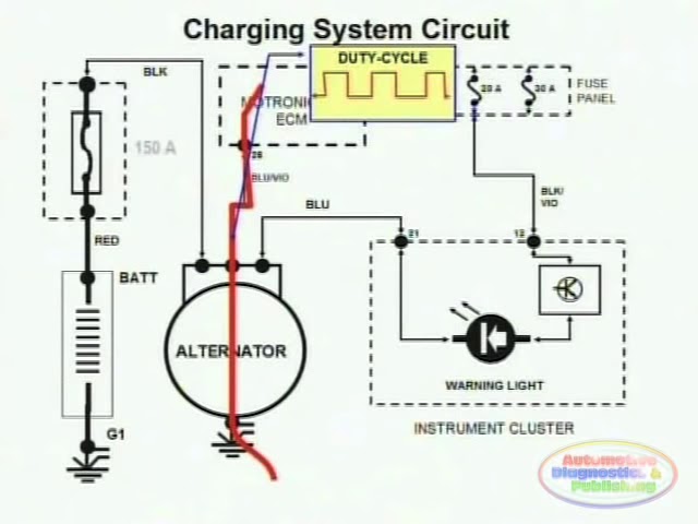
Ford external voltage regulator wiring diagram. External Voltage Regulator Wiring Diagram - alternator external voltage regulator wiring diagram, alternator external voltage regulator wiring diagram pdf, bosch external voltage regulator wiring diagram, Every electrical structure is made up of various different parts. Each component should be set and connected with other parts in specific way. If not, the structure will not work as it ought to Ford alternator regulator wiring diagram effectively read a cabling diagram, one provides to learn how the components inside the method operate. If the voltage is 13.5v or more with the engine running, there is a connection problem downstream. To battery generator 2f428 delco remy 12 volt regulator wiring diagram 5 operate generator at 3500 rpm ... A typical 3-wire alternator wiring diagram with an internal voltage regulator. Computer-Controlled Voltage Regulation Many late-model vehicles use the engine computer, which is often referred to as the powertrain control module (PCM), to control alternator output. It is based upon the lucas mcr2 unit fitted to my bike but is the same for the earlier lucas mcr1 units and also for the later rb107 control box bar a few re ordered connections. Alternator regulator a127. Alternator Voltage Regulator Wiring Diagram Wiring Library So hopefully this article has explained in simple terms […]
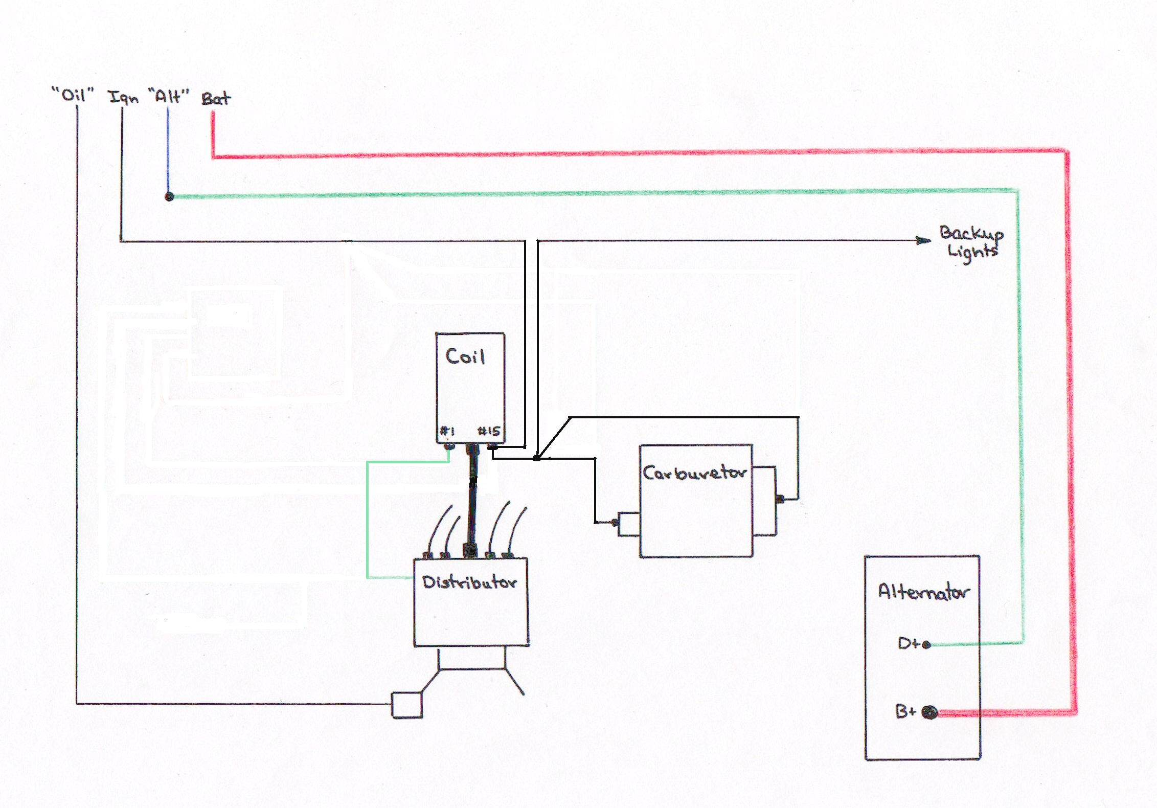
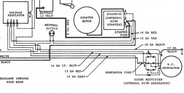
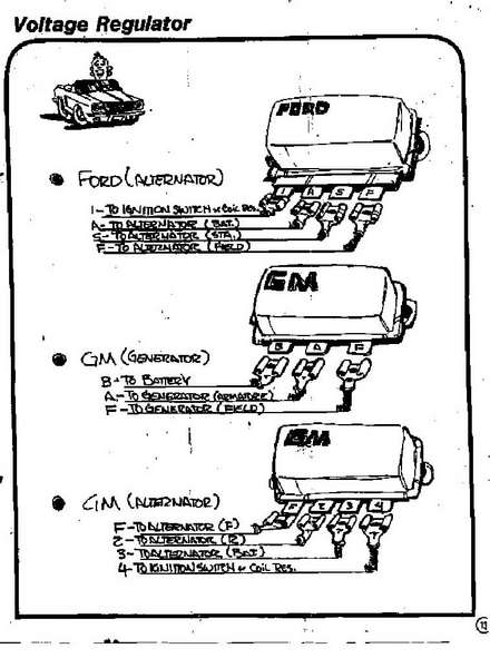
This is how I wire a Ford alternator w/ external regulator, except I delete the amp guage (fire hazard), and use a volt guage. Been wiring then this way for over 30 years with no problems. Last edited: May 24, 2014 Wiring Diagram For Ford External Voltage Regulator. If the voltage is 135v or more with the engine running there is a connection problem downstream. Ford Alternator Wiring Diagram Internal Regulator wiring diagram is a simplified customary pictorial representation of an electrical circuit. Therell be principal lines which are represented by. 30 Jul 2020 — Where can I find the internal schematic for the common Ford external alternator regulator, the one with I A S F terminals?1 answer · 1 vote: Here is the 4 pin diagram, it has never changed over the years for external regulators. A= Battery, to alt and battery. I= Charging indicator on instrument ... Voltage regulator wiring diagram nippondenso. We provide 20 for you about nippondenso alternator wiring diagram page 1. Wiring Diagram for Alternator with External Regulator 82 ford Voltage Regulator Wiring Manual E Book. Nippondenso Alternator Wiring Diagram. Im resurrecting this thread after some trouble.
in todays video we cover how to diagnose a first gen ford alternator and test the alternator or voltage regulator.Tools used in the videoVolt meter: https://... Ford alternator wiring diagram internal regulator among all the ford alternator wiring diagrams above this is the most complicated one. Ford 8N9N Club Your wiring diagram may be a lot more complex due to having a voltage regulator as many later machines had First you cant run to the same side since with the 12 volt conversion we are going to use negative groundA page dedicated to collecting ... 1991 F350 Ford External Voltage Regulator Wiring Diagram. I bought a new 1g (I think) alternator, and I've got two good batteries, and I just bought a new external voltage regulator and I'm about to hook it up. I noticed F IDI I noticed that one wire on the voltage regulator harness (It would hook up to the "A Terminal") is going to nowhere. Make sure the wiring in all circumstances is done accurately since any misconnection will damage your regulator and generator. Mini circuit projects timer circuits emergency light hobby circuits the post explains how to connect common 78xx voltage regulator ics such as 7805 7812 7824 etc in an electronic circuit for getting the intended fixed regulated output voltages at 5v 12v and 24v ...
How To Test An External Voltage Regulator (Pre-73 C10)
Voltage Ford Diagram Wiring Generator Regulatorto - Wiring Diagrams Hubs - Voltage Regulator Wiring Diagram. Wiring diagram also provides beneficial suggestions for assignments that may require some extra equipment. This e-book even consists of recommendations for added supplies that you might need as a way to end your tasks.

Parts Master 84010 6-Wire 4-Terminal External Voltage Regulator Connector for Ford Products
Dimension: 1600 x 1509. DOWNLOAD. Wiring Diagram Sheets Detail: Name: automotive voltage regulator wiring diagram - Alternator Elevation and end view in half sections of an alternator. File Type: JPG. Source: itishiksha.com. Size: 179.91 KB. Dimension: 1280 x 720.

Wiring from and external regulator to an internal reg. alter ...
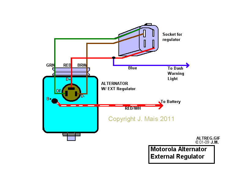
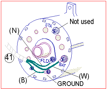
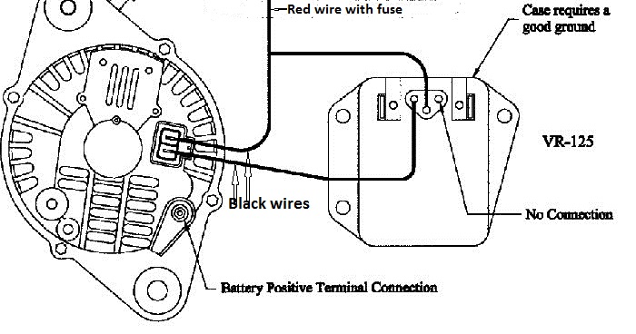
About Regulator External Wiring Voltage Diagram . 3, TAB GND Ground. The Field terminal on the Alt goes to the F terminal on the Voltage Regulator. This wire goes over to the voltage regulator and is going into the terminal marked F on the side of the voltage regulator.

FIGURE 21-1 The digital multimeter should be set to read DC ...
Ford Alternator External Regulator Wiring Diagram | Wiring Diagram - Ford Alternator Wiring Diagram Internal Regulator. Wiring Diagram not merely gives detailed illustrations of everything you can perform, but in addition the procedures you ought to stick to while carrying out so.
Ford Diagrams
I'm attempting to wire up a Ford type alternator in addition to an external Ford regulator. Before my recent engine swap, the truck WAS running a GM/Delco? style 3-wire setup, internally regulated. Explanation of my wiring: I have a ground from alternator ground post to regulator case through one of the mounting holes.
Electrical: Voltage Regulator wiring - Ford Truck Enthusiasts ...
Ford External Voltage Regulator Wiring Diagram. Print the cabling diagram off and use highlighters in order to trace the routine. When you employ your finger or even follow the circuit together with your eyes, it may be easy to mistrace the circuit. 1 trick that I 2 to print out the same wiring diagram off twice.

12V Generator & Voltage Regulator KIT Ford 2000 3000 4000 ...
External Regulator 3 Wire Ford Alternator Wiring Diagram. To properly read a cabling diagram, one has to learn how the components in the method operate. For example , in case a module is powered up and it sends out a new signal of half the voltage in addition to the technician would not know this, he'd think he has a problem, as he would expect ...
old ford regulator alternator question | Hot Rod Forum
VOLTAGE REGULATOR Ford & New Holland Tractor Brand New. $ I'm trying to install a voltage regulator to my jeep cj5 where it's never had one. Thus no separate external regulator. 2 - The wiring diagram in your post is for a Delco 10DN EXTERNALLY regulated alternator.
external voltage regulator? - Dodge Diesel - Diesel Truck ...
Identify My Alternator Vintage Mustang Forums. Ford alternator and an ext voltage wiring with without the regulator w external troubleshooting gm internally regulated electrical 12 volt diagrams regulation 101 g series 12v externally another conversion identify my vintage wire harness installation instructions dodge help 1947 present testing delco 10dn 7000 chrysler negative autolite truck ...

Design and Function of Classic Car Voltage Regulators
Alternator wiring with and without dash light: Back view of a standard Ford alternator. Basic schematic for wiring a Ford alternator with external regulator - with and without warning light. Basic Wiring Primer and Troubleshooting Guide (not finished, but still very useful)
Volkswagen Beetle Questions - Try this again. I have a 1974 ...
EEC-IV Fault Codes: Here we have Ford Wiring Diagrams and related pages. Electronic Fuel Injection. Ford EFI injector wiring conversion (Bank firing to Independently fired) - Figure A 1990 5.0 HO EFI Mustang Wiring - Drawing A Ford 7.4 IDI Diesel Glo-plug controller by-bass wiring.Figure A
Alternator Wiring
Get the Original Quick Start bypass kit from your service tech or we can help you DIY it yourself Demand the better QuickStart kit For the Emergency External...

1971 alternator wiring diagram help - Pelican Parts Forums
The "I" terminal on the voltage regulator goes to the dash "ALT" indicator light. I don't have a diagram handy so I'll describe that circuit as best I can. One wire of the "ALT" light goes ultimately to the "I" terminal on the voltage regulator, the other wire of the "ALT" light ultimately ends up at the ignition switch accessory terminal.

Electrical Systems:How to convert to an external voltage ...
Search: External Voltage Regulator Wiring Diagram. About Voltage Wiring Diagram Regulator External . You will need to try different values for the 57-100K resistor -- this depends on your sensor and soil and you may fall out of this range.

Pin on Auto diagram
Ford 7000 Alternator/Voltage Regulator - TractorByNet
Alternator wiring with and without the dash warning light

By Pass Volt Reg Install Old Style?
Testing Delco 10DN external voltage regulator : Other ...
Charging problem - iRV2 Forums
Alternator/Regulator troubleshooting

Single Wire Alternator Chevy Voltage Regulator Circuit Ac ...

Ford alternator wiring questions - YouTube
/stories/2018/07/43253.jpg)
Voltage Regulators | Hemmings
Identify my alternator | Vintage Mustang Forums
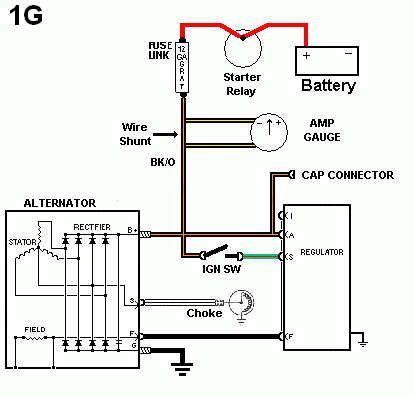
1g and 2g alternator - 4g61t.org
GM & Ford external regulator wiring diagrams. | Ford Explorer ...
Wiring Help Needed; Voltage Regulator/Alternator - Ford Truck ...
Ford externally regulated alternator wiring
Charging System & Wiring Diagram - YouTube
2H Alternator Questions - Identifying a 24v vs 12v Externally ...
I terminel on reg. - Ford Truck Enthusiasts Forums
Alternator Trouble shooting

New Page 1

1974 cherokee: voltage regulator..these wires attach on the ...

33 Alternator ideas | alternator, car alternator, automotive ...

Mustang Voltage Regulator (1968-1970) Installation Instructions
internally regulated alternator w/ external regulator? | Ford ...
Manual Photography
1 wire verse stock multi wire alternator clarification in ...
Converting a Generator to an Internally Regulated Alternator ...
Ford electronic voltage regulator - Ford Truck Enthusiasts Forums


Comments
Post a Comment