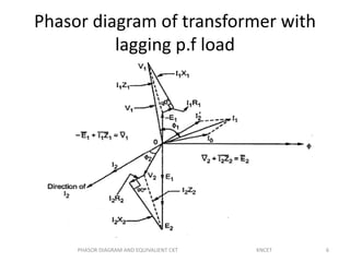
41 Phasor Diagram Of Transformer
RL Series Circuit | Phasor Diagram | Impedance & Power ... The relationship between the current and voltages in a series RL circuit is shown in the vector (phasor) diagram of Figure 2 and can be summarized as follows: The reference vector is labeled I and represents the current in the circuit, which is common to all circuit elements. PDF Chapter 5 | Non-ideal (real) transformer Transformer Nameplate Data. Transformer nameplates contain information about the size of the transformer in terms of how much apparent power (rated in kVA) it Represents reactive power and is called: Magnetizing current. Equivalent circuit of transformer core. Phasor diagram of exciting current.
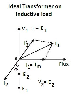
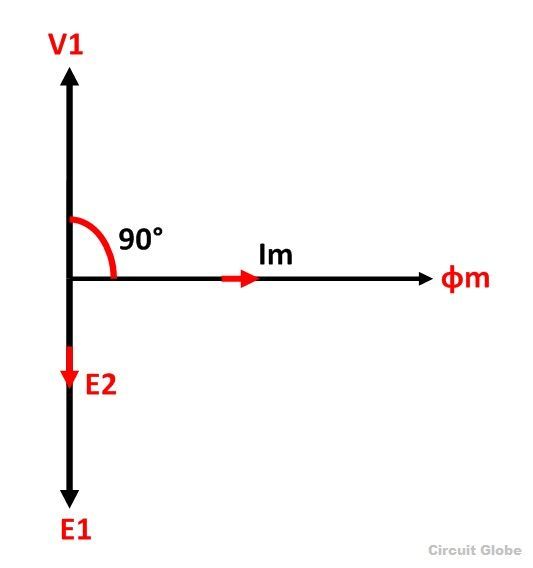
Phasor Diagram of Ideal Transformer The phasor diagram of this transformer with no load is shown below. When the transformer is on the no-load condition, then the current within the secondary coil can be zero that is I2 = 0. In the above figure
Phasor diagram of transformer
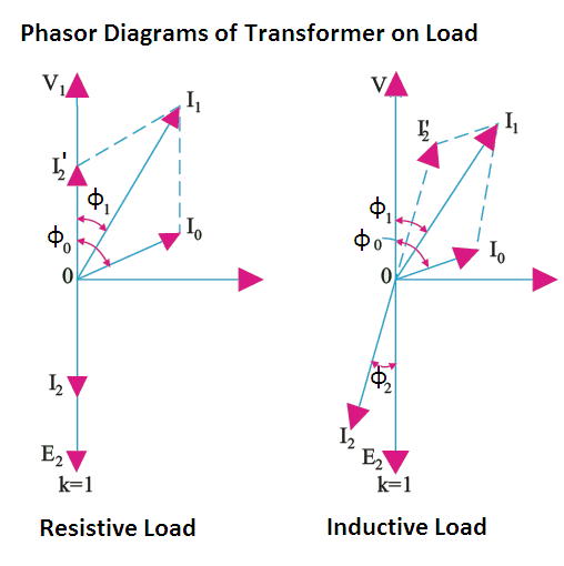
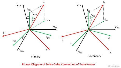
Phasor Diagram Of Transformer Video Lecture on Phasor Diagram of Transformer for Lagging and Loading Load of Chapter Three Phase Circuits of Subject Basic ... transformer_phasor_inductive_load Phasor Diagram of Transformer under Inductive Load is explained in hindi in step by step ... Full Load Phasor Diagram Of Transformer Video Lecture on Phasor Diagram of Transformer for Lagging and Loading Load of Chapter Three Phase Circuits of Subject Basic ... Dear Students, This Video is based on the Phasor Diagram of Transformer for Resistive, Inductive and Capacitive Load You can ... Where and Why Do We Use Phase-Shifting Transformers The phasor diagram has been plotted for no-load conditions, i.e., without considering the voltage drop in the unit. It also should be noted that the currents in the two halves of the series winding are not in phase. This is different from normal power transformers and has consequences with respect to the...
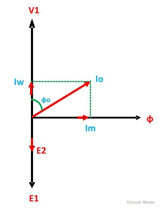
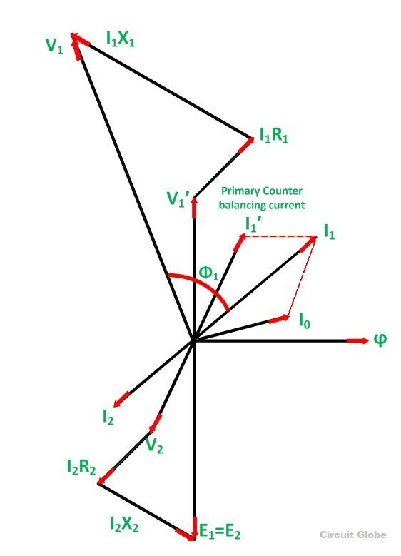
Phasor diagram of transformer. Transformer on NO Load Condition - its Phasor Diagram ... The phasor sum of magnetizing current I m and the working current I w gives the no-load current I 0. From the phasor diagram drawn above, the following conclusions are made: This is all about transformer in no load condition. Real Transformer phasor diagram - GeoGebra © 2022 GeoGebra. Real Transformer phasor diagram. Author What is the transformer phasor diagram? - Quora A phasor diagram represents a rotating vector of two or more sinusoids of differing quantities and of the same frequency, at a single point in time, and The diagram above explains the phasor of an ideal transformer at inductive load. I have also drawn an equivalent circuit of the transformer which... Transformer ON Load Condition - Phasor Diagram on... - Circuit Globe Phasor Diagram of Transformer on Inductive Load. The phasor diagram of the actual transformer when it is loaded inductively is shown below
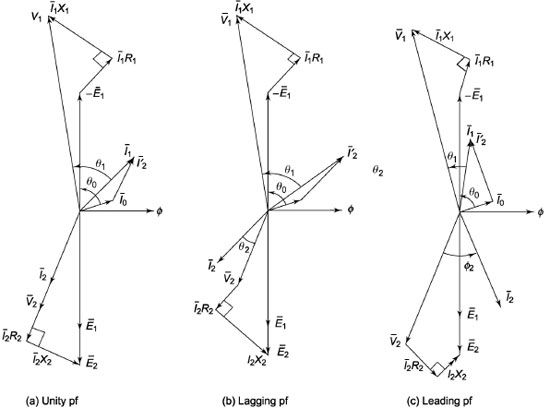
Equivalent circuit and Phasor diagram of a transformer Equivalent circuit of a transformer is a schematic representation of a practical transformer that shows all electrical parameters such as winding resistance, reactance, admittance With reference to the equivalent circuit of the transformer, the phasor diagram of a transformer can be drawn. Practical Transformer on Load - Its Phasor Diagram and Examples Case 1 - When the transformer is assumed to have no winding resistance and leakage flux. The figure shows a practical transformer with the assumption that The phasor diagram shows that both the emfs E1 and E2 lag behind the mutual flux (ϕm) by 90°. The current I'2 denotes the portion of primary... Implement phasor model of three-phase OLTC regulating transformer... The regulating transformer is associated with a control system which regulates voltage at the transformer terminals (side 1 or side 2) or at a remote bus. Such a control system is provided in the Three-Phase OLTC Regulating Transformer (Phasor Type) block. Phasor - Wikipedia In physics and engineering, a phasor (a portmanteau of phase vector), is a complex number representing a sinusoidal function whose amplitude (A), angular frequency (ω), and initial phase (θ)...
RLC Series circuit, phasor diagram with solved problem Sep 27, 2018 · The same thing is represented with the phasor diagram. The above vectors from the above diagram can be added vectorially which will get us the voltage triangle. The vertical component of the triangle shows the voltage drop across reactance (inductive and capacitive) and the horizontal component shows a drop across the resistance. Vector Groups of Transformer: ELECTRICAL ENGINEERING MATERIALS Oct 14, 2018 · A poly phase transformer with HV winding in Delta, LV winding in star with neural and the LV line phasor 1 O’clock i.e. 30° behind of the zero hour position of the HV line phasors. As shown in the above figure the transformer is having 3 phases on HV Side (1U,1V,1W) and 3 Phases on LV Side (2U,2V,2W). PDF Microsoft PowerPoint - Phasors_Final_3_9_2012_Ron_Alexander.ppt... In the phasor diagram, everything is plotted on a coordinate system. Phasors are defined relative to the 'reference phasor' which is always chosen to point to If you had to do this from a transformer nameplate, you generally only see the bushing designations and it's polarity (additive or subtractive). RL Circuit : Derivation, Response Factors, Phasor Diagram ... Jul 23, 2021 · To draw a phasor diagram for the circuit, below are the steps to be followed. Consider, the current ‘I’ as a reference point; The voltage drop that takes place across resistor V R = I R is drawn in the exact phase with that of current ‘I’.
Ideal Transformer on Load - your electrical guide
Phasor Analysis of Transformer Circuits | Basic Alternating Current... Phasors are to AC circuit quantities as polarity is to DC circuit quantities, and for this reason they are particularly useful in analyzing transformer The secondary phasor must remain locked at the same angle as the primary phasor, but its position on the diagram is determined by where the transformer...

Transformer Loading and On-load Phasor Diagrams
Phasor Diagram - an overview | ScienceDirect Topics Time phasor diagrams for one phase winding under no-load and loaded conditions are shown in Fig. 9.17 A and B , respectively, and in each case the time phasors of Figure 14.1 . Phasor diagram for single phase 1:1 turns ratio transformer supplying an inductive load of lagging power factor cos θ 2 .

Transformer ON Load Condition - Phasor Diagram & Operation
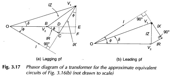
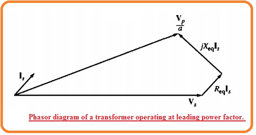
PDF EE 340 Power Transformers A transformer phasor diagram is a graphical representation of this equation. Transformer phasor diagram. A transformer operating at a lagging power factor: It is seen that Vp/a > Vs, VR > 0.
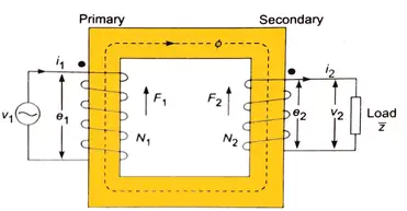
Equivalent circuit and Phasor diagram of a transformer
Autotransformer phasor diagram | Physics Forums I'm studying Auto Transformer phasor diagram, and am having some doubts. I'd be grateful if someone could help me out with them. Book has equation: I...

Equivalent circuit and Phasor diagram of a transformer
Phasor Diagram of Transformer | PDF | Transformer Phasor Diagram Of Transformer - Free download as PDF File (.pdf), Text File (.txt) or view presentation slides online. How to draw and objectives of Phasor Diagram of transformer.
Ideal Transformer on Load - your electrical guide
Phasor diagram ( inductive load) for a single phase... A complete guide to drawing phasor diagram for a single phase transformer connected to an inductive load. Highly animated video for simple understanding.
Potential Transformer : Construction and Its Applications
Understanding Vector Group of Transformer (part 1) Feb 15, 2022 · Introduction. Three phase transformer consists of three sets of primary windings, one for each phase, and three sets of secondary windings wound on the same iron core.Separate single-phase transformers can be used and externally interconnected to yield the …
Phasor diagram
Transformer Loading and On-load Phasor Diagrams Sep 01, 2013 · We can show this relationship as a phasor diagram. Transformer Loading Current . If we are given currents, I S and Io, we can calculate the primary current, I P by the following methods. Transformer Loading Example No2. A single phase transformer has 1000 turns on its primary winding and 200 turns on its secondary winding. The transformers ...

Transformers | Galoms
Phasor Diagram of Transformer on No Load - EEEGUIDE.COM Figure 3.5 shows the schematic diagram of a Phasor Diagram of Transformer on No Load with Two Winding, i.e. the secondary terminals are open while the primary is connected to a source of constant sinusoidal voltage of frequency fHz. The simplifying assumption that the resistances of the windings...
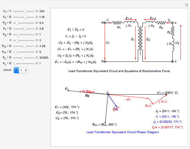
Circuit Phasor Diagram for Transformers - Wolfram ...
Direction of E1 and E2 in phasor diagram of transformer The phasor diagram of transformer is a bit confusing. Is E1 and E2 have same direction? Different books mention it differently. If primary winding and secondary windings are wound in the same way then E1 and E2 will be in phase. Consider this diagram and the first three scenarios
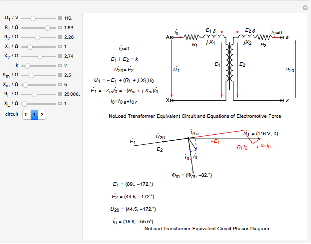
Circuit Phasor Diagram for Transformers - Wolfram ...
Circuit Phasor Diagram for Transformers - Wolfram Demonstrations... This Demonstration shows the equivalent circuit phasor diagram for a transformer A power source supplies a voltage that is some combination of sine waves represented by a phasor diagram For the phasor diagram would be a unit vector rotating about the origin A more complex circuit gives a...
Phasor diagram of transformer on load? - Quora
Phasor Diagrams 11. Transformers. Phasor Diagrams Show Phase Difference. Every phasor in the diagram will have the same angular velocity because they represent sine waves of identical frequency.
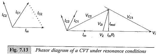
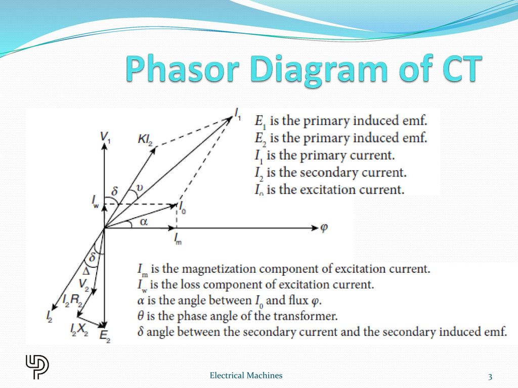
Capacitance Voltage Transformer | Phasor Diagram of CVT
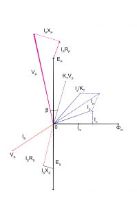
Transformer Phasor Diagram - ELECTRICAL TECHNOLOGY AND... Transformer Phasor Diagram_Step 5: Sum of V2, I2R2, I2X2 shall form induced voltage at secondary winding i.e. E2. As mentioned this is a vector sum So, by these we can draw the phasor diagram of a transformer. Understanding of this is very important for understanding the transformer working...
Three-Phase Transformer Connections - Circuit Globe
PDF test_2.docx Now give examples of transformers connection, their potential phasor diagrams with indicated vector groups. Figure 3 Potential diagram of transformer Basing on the way of transformer connection and the potential diagram, find the transformer connection symbol: Y/Y-6.

PHASOR DIAGRAM ( INDUCTIVE LOAD) FOR A SINGLE PHASE TRANSFORMER
Open Circuit and Short Circuit Test on Transformer ... Phasor Diagram of Short Circuit Test. From the phasor diagram. Equivalent impedance referred to the secondary side is given by. The equivalent reactance referred to the secondary side is given by. The voltage regulation of the transformer can be determined at any load and power factor after knowing the values of Z es and R es.
Phasor Diagram of Transformer - EEEGUIDE.COM
Three Phase Transformer Connections Phasor Diagrams ... Conversely, the ∆-Y connection is used for stepping up to a high voltage, as in generation station transformer. Fig.1 (c): Delta-Wye Three Phase Transformer Connection. Fig.1 (c): Delta-Wye Three Phase Transformer Phasor Diagram. Advantages of Delta-Wye Connection. Balanced connection when supplying 1-φ and 3-φ loads

Transformer Phasor Diagram for No Load Condition
Phasor Diagram of Transformer - Electrical Concepts Important Points for Phasor Diagram of Transformer: 1) Transformer when excited at no load, only takes excitation current which leads the working Flux by Hysteretic angle α. 2) Excitation current is made up of two components, one in phase with the applied Voltage V is called Core Loss component...
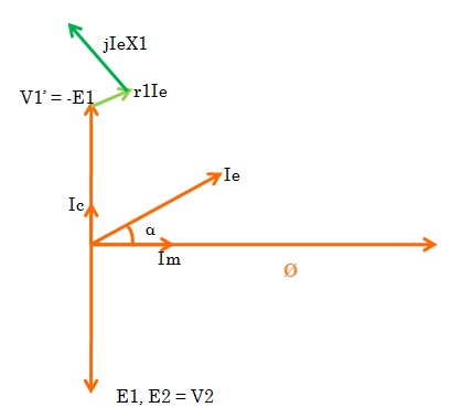
Phasor Diagram of Transformer - Electrical Concepts
Three-Phase Transformer Connections (Wiring Diagrams ... Aug 29, 2021 · The phasor diagram of delta-star connection for lagging power factor and balanced load condition is as shown in the figure below. Phasor Diagram Delta-Star (Δ-Y) Connection As shown in the phasor diagram, secondary phase voltage V aN leads to primary voltage V AN by 30˚.
Transformer on NO Load Condition - its Phasor Diagram ...
Phasor Diagram Creator Loading... Phasor Diagram Creator. Log InorSign Up. Add two phasors below, where the voltages and phases will be added and displayed.

Potential Transformers - Engineering Notes Online
Transformer Phasor Diagram - Electrical Machines... - Sanfoundry Electrical Machines Questions and Answers - Transformer Phasor Diagram. This set of Electrical Machines Multiple Choice Questions & Answers (MCQs) focuses on "Transformer Phasor Diagram". 1. The output voltage seen at the CRO connected at the secondary terminals is square wave.
Three Phase Transformer Connections Phasor Diagrams ...
Where and Why Do We Use Phase-Shifting Transformers The phasor diagram has been plotted for no-load conditions, i.e., without considering the voltage drop in the unit. It also should be noted that the currents in the two halves of the series winding are not in phase. This is different from normal power transformers and has consequences with respect to the...

Open Circuit Test and Short Circuit Test on Transformer( SC/OC)
Full Load Phasor Diagram Of Transformer Video Lecture on Phasor Diagram of Transformer for Lagging and Loading Load of Chapter Three Phase Circuits of Subject Basic ... Dear Students, This Video is based on the Phasor Diagram of Transformer for Resistive, Inductive and Capacitive Load You can ...

Transformer ON Load Condition - Phasor Diagram & Operation
Phasor Diagram Of Transformer Video Lecture on Phasor Diagram of Transformer for Lagging and Loading Load of Chapter Three Phase Circuits of Subject Basic ... transformer_phasor_inductive_load Phasor Diagram of Transformer under Inductive Load is explained in hindi in step by step ...
Equivalent Circuit of Transformer Referred to Primary and ...
Phasor Diagram of Transformer - EEEGUIDE.COM

Complete Knowledge database of Electricity and Electrical ...
Transformer Voltage Regulation and Efficiency - The ...

Potential Transformer: 8 Important Topics Asked In Exams

Vector Diagram of Transformer: What it is & How To Draw ...

Theory of Transformer on Load and No Load Operation ...

Guide to Industrial Power Transformers--Theory
Transformer ON Load Condition - Phasor Diagram on Various ...
CHAPTER 6 SPECIAL TRANSFORMERS Electrical Machines. - ppt ...

No load Transformer and its phasor diagram - Electrical ...
The Exact Equivalent Circuit
What is a Current Transformer? Construction, Theory of ...

Transformer Phasor Diagram - ELECTRICAL TECHNOLOGY AND ...
What is an Ideal transformer? - its Phasor Diagram - Circuit ...

Transformer ON Load Condition - Phasor Diagram & Operation
Transformer With Resistance And Leakage Reactance ...

Phasor Diagram And Equivalent Circuit Of A Single Phase ...


Comments
Post a Comment