40 tanabe-sugano diagram
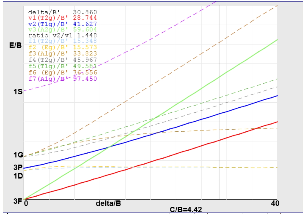
TanabeSugano. A python-based Eigensolver for Tanabe-Sugano- & Energy-Correlation-Diagrams based on the original three proposed studies of Yukito Tanabe and Satoru Sugano for d 2-d 8 transition metal ions:. On the Absorption Spectra of Complex Ions. A series of JAVA applets of Tanbe-Sugano diagrams were developed by Prof. Robert Lancashire at the University of the West Indies. These diagrams allow students to determine delta o /B values based on ratios of peak energies without the pain of rulers and drawing lines. There are also features that allow a person to input values and automatically calculate certain parameters.
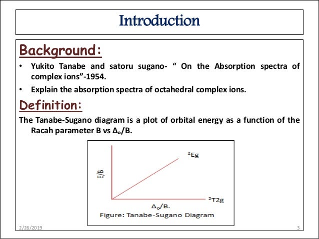
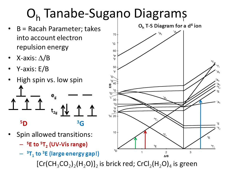
2 • Tanabe-Sugano diagrams have been calculated for d the cases of all ligand field strengths for all octahedral dn-metal complex configurations. • The diagrams allow for estimation of a complete set of parameters included in the calculations: i) the (apparent) electron repulsion parameter B', ii) D, iii) transition frequencies.

Tanabe-sugano diagram
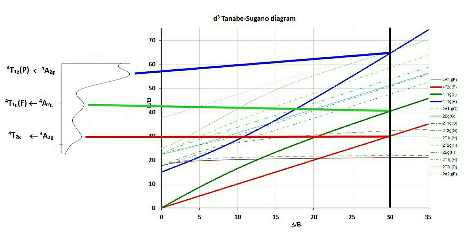
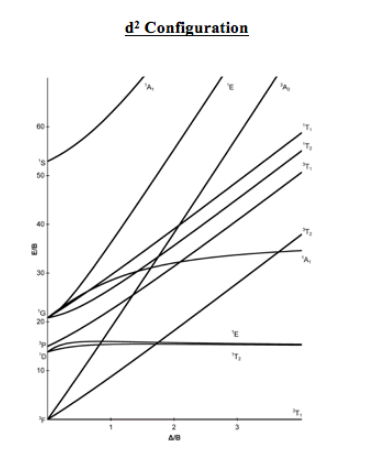
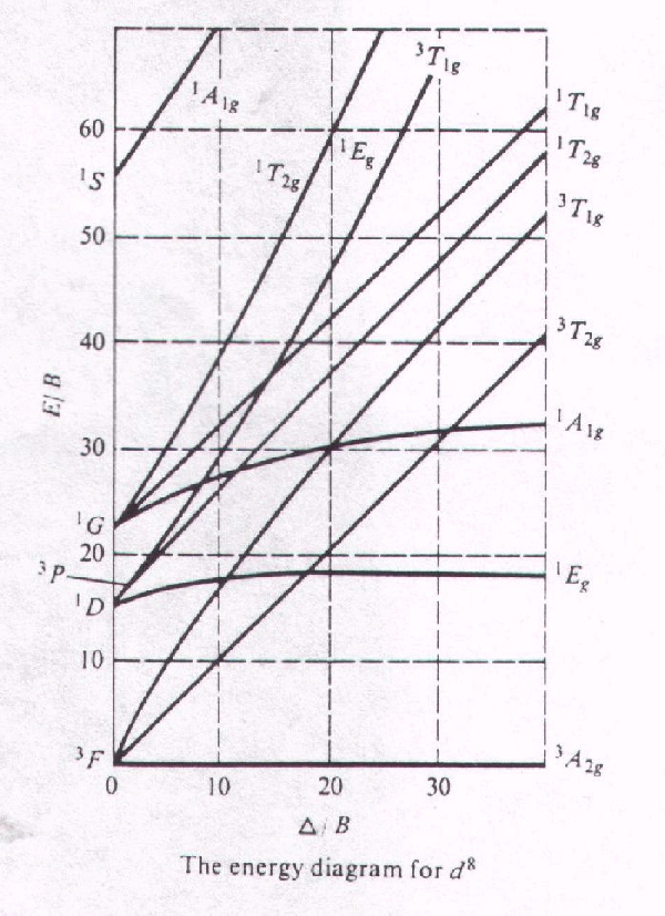
T sdiagram. 1. d2 Tanabe-Sugano Diagram 1A 1E 1g g 80 3A 2g 70 60 1T 1g 1T 1S 2g 3T 50 1g E/B 40 3T 2g 1A 1g 30 1G 20 1E 3P g 1D 1T 2g 10 3F 3T 0 1g 0 10 20 30 40 ∆o/B. 2. d3 Tanabe-Sugano Diagram 4T 1g A2g 2 80 70 2A 1g 4T 60 1g 50 4T 2g E/B 40 2F 2T 2g 30 2T 1g 20 2E 2G g 4P 10 4F 4A 0 2g 0 10 20 30 40 50 ∆o/B. 15 Aug 2020 — Tanabe-Sugano diagrams are used in coordination chemistry to predict electromagnetic absorptions of metal coordination compounds of ... Tanabe-Sugano diagrams are used in coordination chemistry to predict electromagnetic absorptions of metal coordination compounds of. Tanabe-Sugano diagram for d3 octahedral complexes. TS d3 diagram. Interpolation of the graph to find the Y-axis values for the spin-allowed transitions gives.
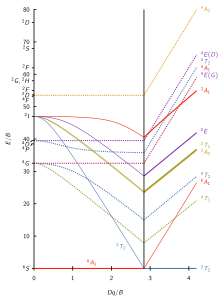
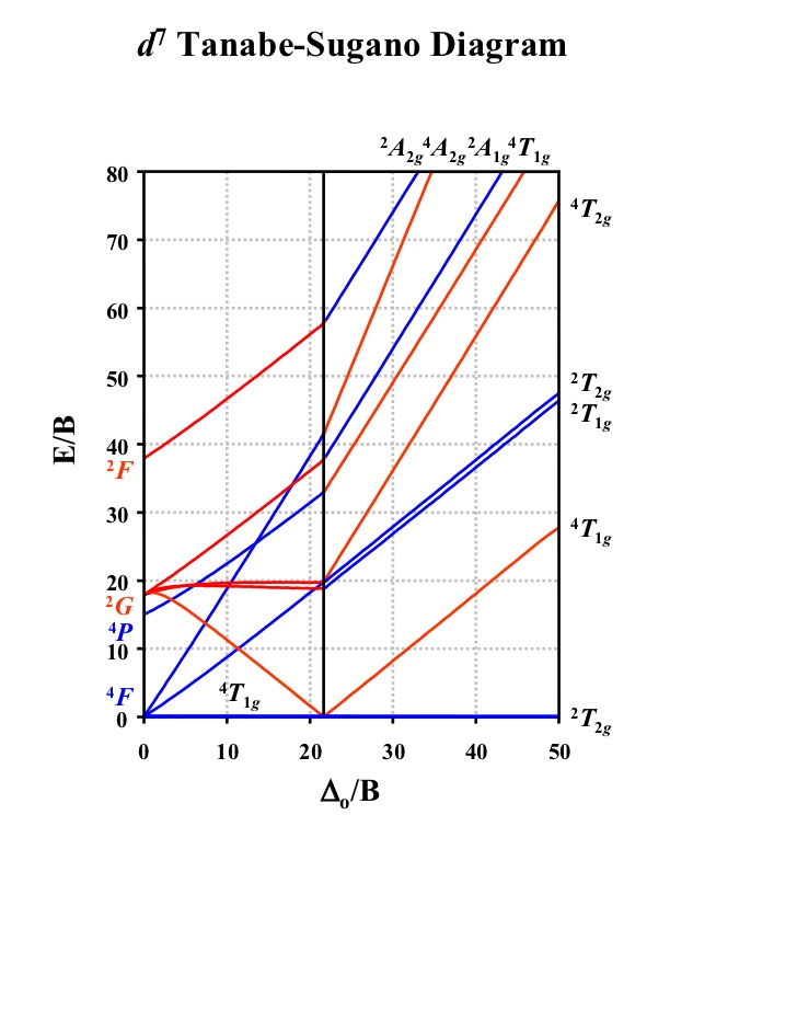
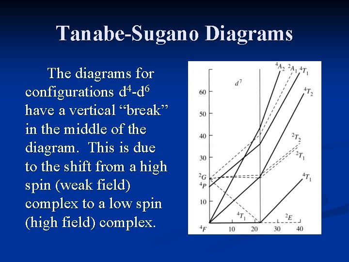
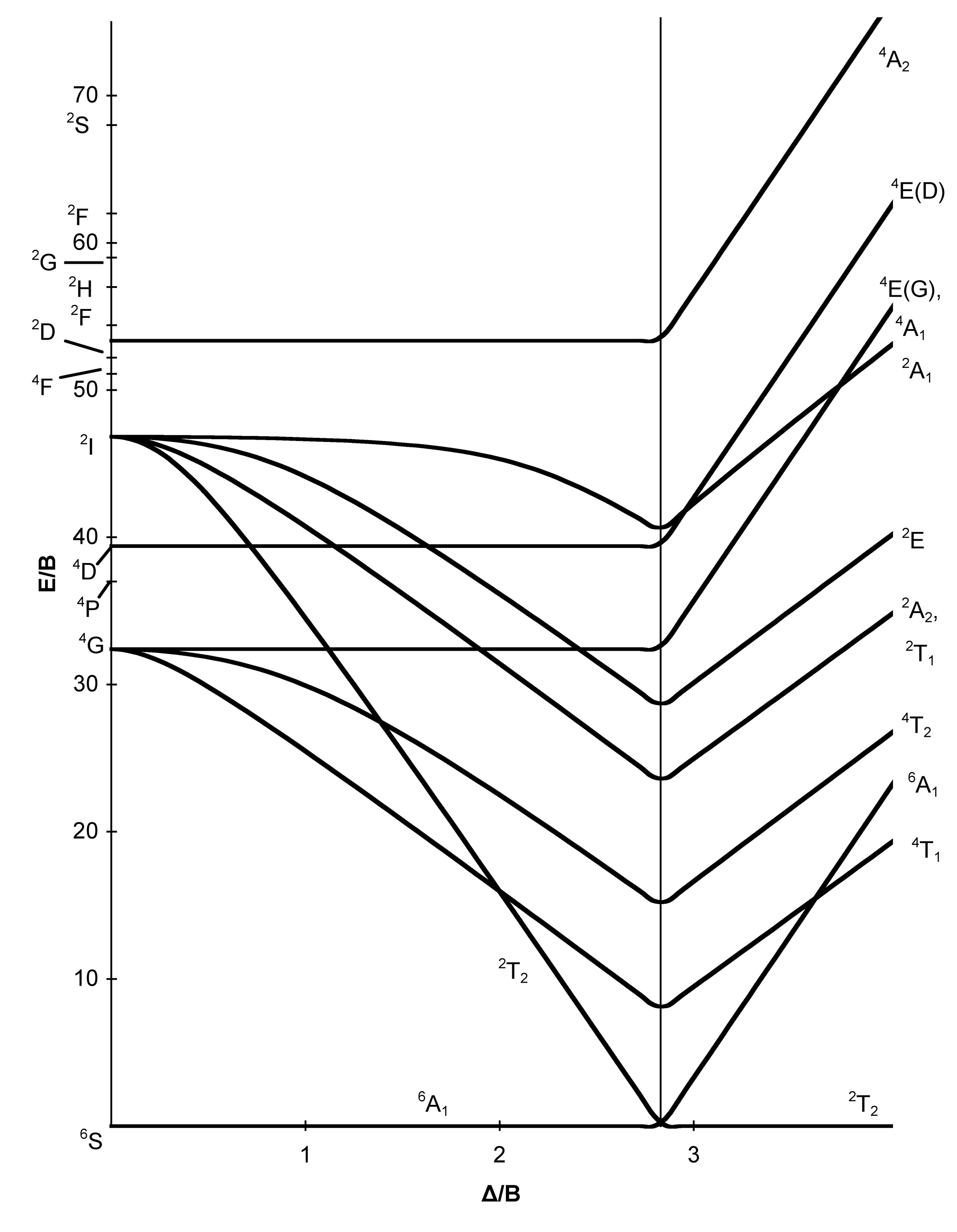
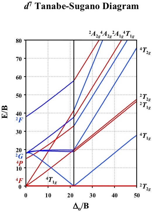
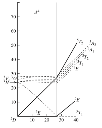
Tanabe-sugano diagram. d7Tanabe-Sugano Diagram E / B ∆o/ B 4F 2G 2Eg 2T1g 2A1g 2T2g 4P 4A2g 4T1g (4P) 4T2g 4T1g (4F) small ∆o High Spin large ∆o Low Spin Complexes with d4-d7 electron counts are special •at small values of ∆o/B the diagram looks similar to the d2diagram •at larger values of ∆o/B, there is a break in the diagram leading to a new ground ... Certain Tanabe-Sugano diagrams (d 4, d 5, d 6, and d 7) also have a vertical line drawn at a specific Dq/B value, which is accompanied by a discontinuity in the slopes of the excited states' energy levels.This pucker in the lines occurs when the identity of the ground state changes, shown in the diagram below. The left depicts the relative energies of the d 7 ion states as functions of ... 9 Oct 2020 — Tanabe-Sugano diagrams are used in coordination chemistry to predict electromagnetic absorptions of metal coordination compounds of ... A step-by-step tutorial on assigning the transitions in the UV-vis spectrum of a d7 system using a Tanabe-Sugano Diagram.
Tanabe-Sugano diagrams via spreadsheets A set of spreadsheets has been developed to aid in spectral interpretation. for d2 (oct) for d3 (oct) for d4 (oct) for d5 (oct) for d6 (oct) for d7 (oct) for d8 (oct) Alternatively a single ZIP file containing all of the above spreadsheets can be downloaded. See the instructions for more information. Advantages over Orgel diagrams • Tanabe-Sugano diagrams can be used for both high spin and low spin complexes, unlike Orgel diagrams which apply only to high spin complexes. • In a Tanabe-Sugano diagram, the ground state is used as a constant reference, in contrast to Orgel diagrams. For other uses of "T-S diagram", see Temperature entropy diagram.. Tanabe-Sugano diagrams are used in coordination chemistry to predict absorptions in the UV and visible are used in coordination chemistry to predict absorptions in the UV and visible d2 Tanabe-Sugano Diagram 1A 1E 1g g 80 3A 2g 70 60 1T 1g 1T 1S 2g 3T 50 1g E/B 40 3T 2g 1A 1g 30 1G 20 1E 3P g 1D 1T 2g 10 3F 3T 0 1g ∆o/B 0 10 20 30 40 d3 Tanabe-Sugano Diagram 4T 2 1g A2g 80 70 2A 1g 4T 60 1g 50 4T 2g E/B 40 2F 2T 2g 30 2T 1g 20 2E 2G g 4P 10 4F 4A 0 2g ∆o/B 0 10 20 30 40 50 d4 Tanabe-Sugano Diagram 3A 1 2g A2
Using Tanabe-Sugano diagrams — Tanabe-Sugano diagrams were developed in the 1950's to give a semi-quantitative approach and include both high and ... Tanabe-Sugano diagrams are used in coordination chemistry to predict electromagnetic absorptions of metal coordination compounds of. The different free ion terms for an electron configuration have different energies due to variations in electron-electron repulsion. The different. Tanabe-Sugano diagrams do not have this restriction and can be applied to the situations when Δ is significantly greater than inter-electronic repulsion. Thus, the Tanabe-Sugano diagrams can be utilized in determining electron placements for high-spin and low-spin metal complexes. Tanabe-Sugano Diagram - Parameters Parameters The x-axis of a Tanabe–Sugano diagram is expressed in terms of the ligand field splitting parameter, Dq, or Δ, divided by the Racah parameter B. The y-axis is in terms of energy, E, also scaled by B. Three Racah parameters exist, A, B, and C, which describe various aspects of interelectronic repulsion.
Electronic Structure
田边-菅野图(Tanabe-Sugano图)用于预测配合物的紫外和可见光谱。预测结果与光谱实验结果对比,可估算配体场分裂能10Dq的大小。高自旋和低自旋配合物的谱学性质都可用田边-菅野图来预测,不同于只能预测高自旋的Orgel图。也可用其预测致高自旋至低自旋的跃迁的配体场大小。

d 3 Tanabe–Sugano diagram for Cr 3+ ion in octahedral ...
Tanabe-Sugano diagram Tanabe-Sugano diagrams are used in coordination chemistry to predict absorptions in the UV, visible and IR electromagnetic spectrum of coordination compounds. The results from a Tanabe-Sugano diagram analysis of a metal complex can also be compared to experimental spectroscopic data. They
Solved 1. Using the optical absorption spectra of | Chegg.com
3 Feb 2021 — 20.7G: Help on using Tanabe-Sugano diagrams · Record the UV/Vis spectrum of your sample. · Tabulate peak information in wavelengths (nm) and ...
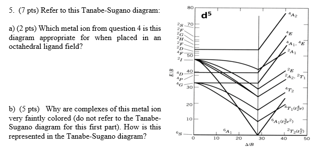
Solved 5. (7 pts) Refer to this Tanabe-Sugano diagram: gs a ...
Tanabe–Sugano diagrams are used in coordination chemistry to predict absorptions in the UV, visible and IR electromagnetic spectrum of coordination compounds. The results from a Tanabe–Sugano diagram analysis of a metal complex can also be compared to experimental spectroscopic data.
Tanabe–Sugano diagram - Wikipedia
Lecture 4 May Tanabe Sugano Diagrams A Tanabe-Sugano (TS) diagram plots the energy dependence of the various ligand field states (or terms) with field strength. The strength of the ligand field is defined by Dq, which is related to the octahedral crystal field splitting by 10Dq = ∆o. The energy of the state is given by E.
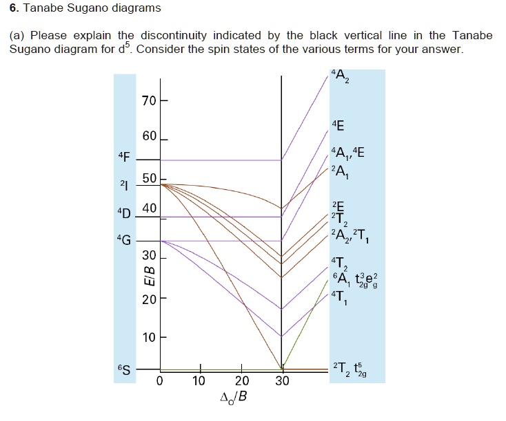
SOLVED:6. Tanabe Sugano diagrams (a) Please explain the ...
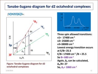
d2Tanabe-Sugano Diagram E / B ∆o/ B 3F 3P 3T 1g (3P) 3A 1g 3T 2g (3F) 3T 1g ~15B ~∆o ~∆o E1 E2 E3 E is the energy of the excited state relative to the ground state B is the Racah parameter for e–-e–repulsion The example on page 427 of your text shows how to use this chart to fit the experimental data (E1, E2, and E3) for [V(OH2)6]3+to ...
Solved] Consider the Tanabe-Sugano Diagram for a d3 metal ...
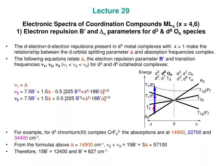
The baseline in the Tanabe-Sugano diagram represents the lowest energy or ground term state. The d2 case (not many examples documented). The electronic spectrum of the V 3+ ion, where V (III) is doped into alumina (Al 2 O 3 ), shows three major peaks with frequencies of: ν1=17400 cm -1, ν2=25400 cm -1 and ν3=34500 cm -1.
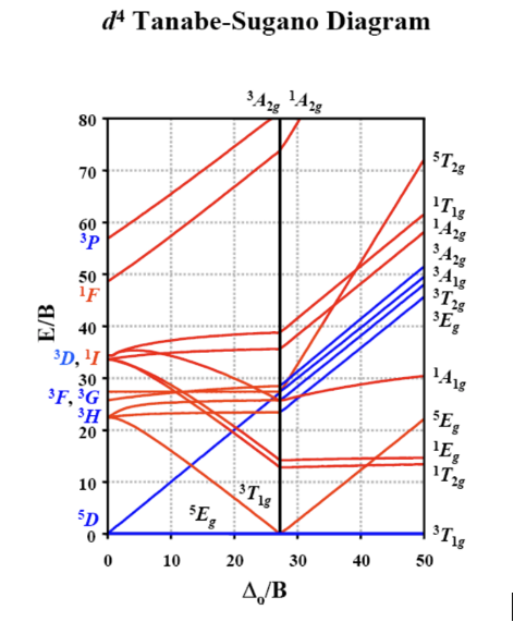
Answered: dª Tanabe-Sugano Diagram 80 70 60 3P 50… | bartleby
Orgel and Tanabe-Sugano Diagrams for Transition Metal Complexes (d1- d9States) It is a well-known fact that electronic transitions are always accompanied by vibrational as well as rotational changes which results in a considerable broadening of the bands in the UV-visible spectra of transition metal complexes too.
G - Tanabe-Sugano diagrams. â–« A Tanabe-Sugano diagram is a ...
Lecture 4 May Tanabe Sugano Diagrams A Tanabe-Sugano (TS) diagram plots the energy dependence of the various ligand field states (or terms) with field strength. The strength of the ligand field is defined by Dq, which is related to the octahedral crystal field splitting by 10Dq = ∆o. The energy of the state is given by E.

Transition Metals, Compounds and Complexes or - ppt video ...
5 Jun 2019 — Tanabe-Sugano diagrams are used in coordination chemistry to predict electromagnetic absorptions of metal coordination compounds of ...
Interpretation of the spectra of first-row transition metal ...
Tanabe Sugano Diagram Though it is possible to add low-spin states to an Orgel Diagram, Tanabe Sugano diagrams are commonly used instead for interpretation of spectra including both weak and strong fields. Tanabe Sugano diagrams are similar to Orgel diagrams in that they show how energy levels change with Δo, but they differ in several ways: 1.
Solved 2. Using the Tanabe-Sugano diagram for the d'ion ...
Lecture 4 May 11: Tanabe Sugano Diagrams A Tanabe-Sugano (TS) diagram plots the energy dependence of the various ligand field states (or terms) with field strength. The strength of the ligand field is defined by Dq, which is related to the octahedral crystal field splitting by 10Dq = ∆o. The energy of the state is given by E.

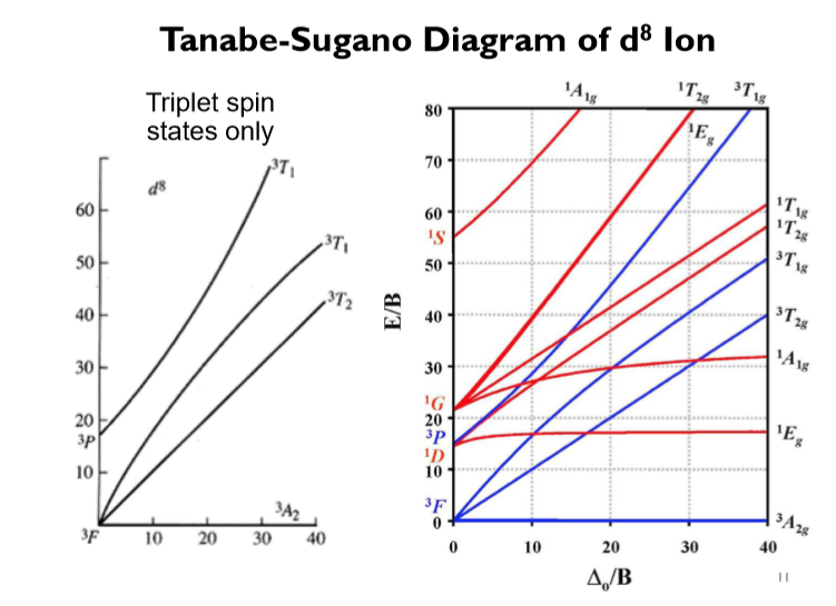
Tanabe-Sugano diagram for the d 8 electron configuration in ...
Title: Microsoft PowerPoint - handout6b Author: Alan Jircitano Created Date: 11/22/2004 11:06:49 PM
Coordination Chemistry III: Tanabe-Sugano Diagrams and Charge ...
Tanabe-Sugano diagrams are used in coordination chemistry to predict absorptions in the UV, visible and IR electromagnetic spectrum of coordination compounds.The results from a Tanabe-Sugano diagram analysis of a metal complex can also be compared to experimental spectroscopic data.

File:Tanabe Sugano Diagram d4.svg - Wikipedia
Aug 15, 2020 · The x-axis in a Tanabe-Sugano diagram is in terms of the crystal field splitting parameter, 10Dq, or Δ oct, scaled by the B Racah Parameter. The y-axis is in terms of energy of a electronic transition, E, scaled by B. Each line represents the energy of an electronic state while varying the strength of octahedral ligand field.
Solved Examine the Tanabe-Sugano diagram for the d2 | Chegg.com
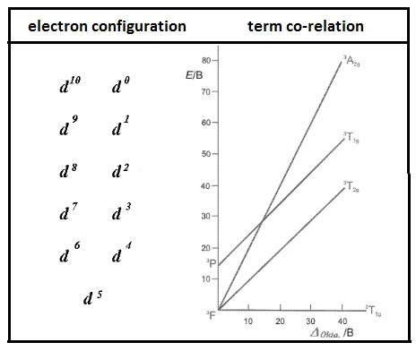
TANABE-SUGANO DIAGRAMS. Tanabe-Sugano diagrams show both low-spin and high-spin cases, and also show spin-forbidden transitions. They even show terms that are near to, but not the ground state! Also, as previously mentioned, there is a hole formalism that says that a dn diagram for octahedral complexes applies to d10−n tetrahedral complexes.

Tanabe Sugano Diagram - d7 system
Tanabe-Sugano diagrams are used in coordination chemistry to predict electromagnetic absorptions of metal coordination compounds of. Tanabe-Sugano diagram for d3 octahedral complexes. TS d3 diagram. Interpolation of the graph to find the Y-axis values for the spin-allowed transitions gives.
The Electronic Spectra of Coordination Compounds The UVVis
15 Aug 2020 — Tanabe-Sugano diagrams are used in coordination chemistry to predict electromagnetic absorptions of metal coordination compounds of ...

Tanabe Sugano
T sdiagram. 1. d2 Tanabe-Sugano Diagram 1A 1E 1g g 80 3A 2g 70 60 1T 1g 1T 1S 2g 3T 50 1g E/B 40 3T 2g 1A 1g 30 1G 20 1E 3P g 1D 1T 2g 10 3F 3T 0 1g 0 10 20 30 40 ∆o/B. 2. d3 Tanabe-Sugano Diagram 4T 1g A2g 2 80 70 2A 1g 4T 60 1g 50 4T 2g E/B 40 2F 2T 2g 30 2T 1g 20 2E 2G g 4P 10 4F 4A 0 2g 0 10 20 30 40 50 ∆o/B.

Invisible spin allowed transitions in Tanabe-Sugano diagrams ...

Tanabe-Sugano diagram for the d 3 electron configuration in ...
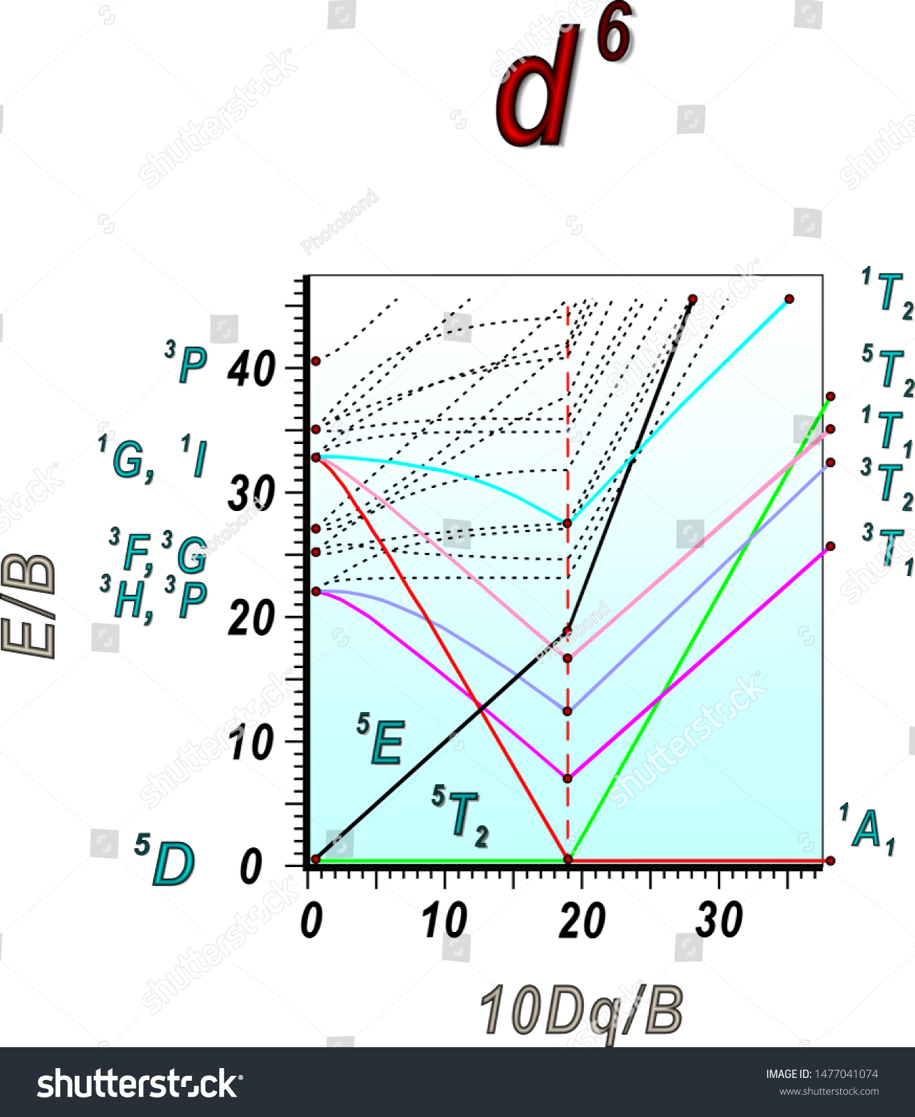
Tanabesugano Diagram Octahedral Complexes D6 Electronic Stock ...
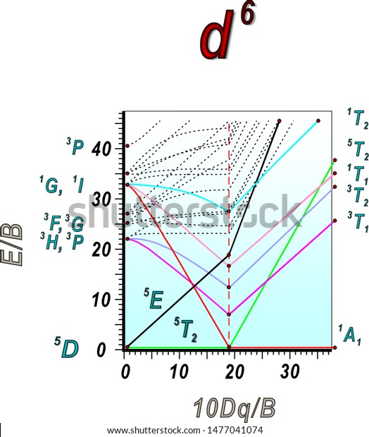
Tanabesugano Diagram Octahedral Complexes D6 Electronic Stock ...
Tanabe sugano diagram
Resources for Crystal field and Ligand Field Calculations
Interpretation of the Emission Spectra of Trivalent Chromium ...
Coordination Chemistry III: Tanabe-Sugano Diagrams and Charge ...
Coordination Chemistry III: Tanabe-Sugano Diagrams and Charge ...
Tanabe sugano diagram

Tanabe–Sugano diagram for the d 5 electron configuration. 19 ...
Tanabe-Sugano Diagrams - Chemistry LibreTexts
Tanabe-Sugano Diagrams - Chemistry LibreTexts
Five Slides About: UV-Vis Spectroscopy and Tanabe-Sugano ...
Interpretation of the spectra of first-row transition metal ...
PPT - 2) Tanabe-Sugano diagrams. d 2 octahedral complexes ...

Tanabe–Sugano diagram - Wikiwand
Tanabe-Sugano Diagram Jahn-Teller Effect
SOLVED:Tanabe-Sugano Diagram 2Azg Azg Alg Tlg ATwa 80 70 60 ...
Explain the difference between Orgel and Tanabe-Sugano ...
Explain the difference between Orgel and TanabeSugano class ...


Comments
Post a Comment