43 auto meter wire diagram
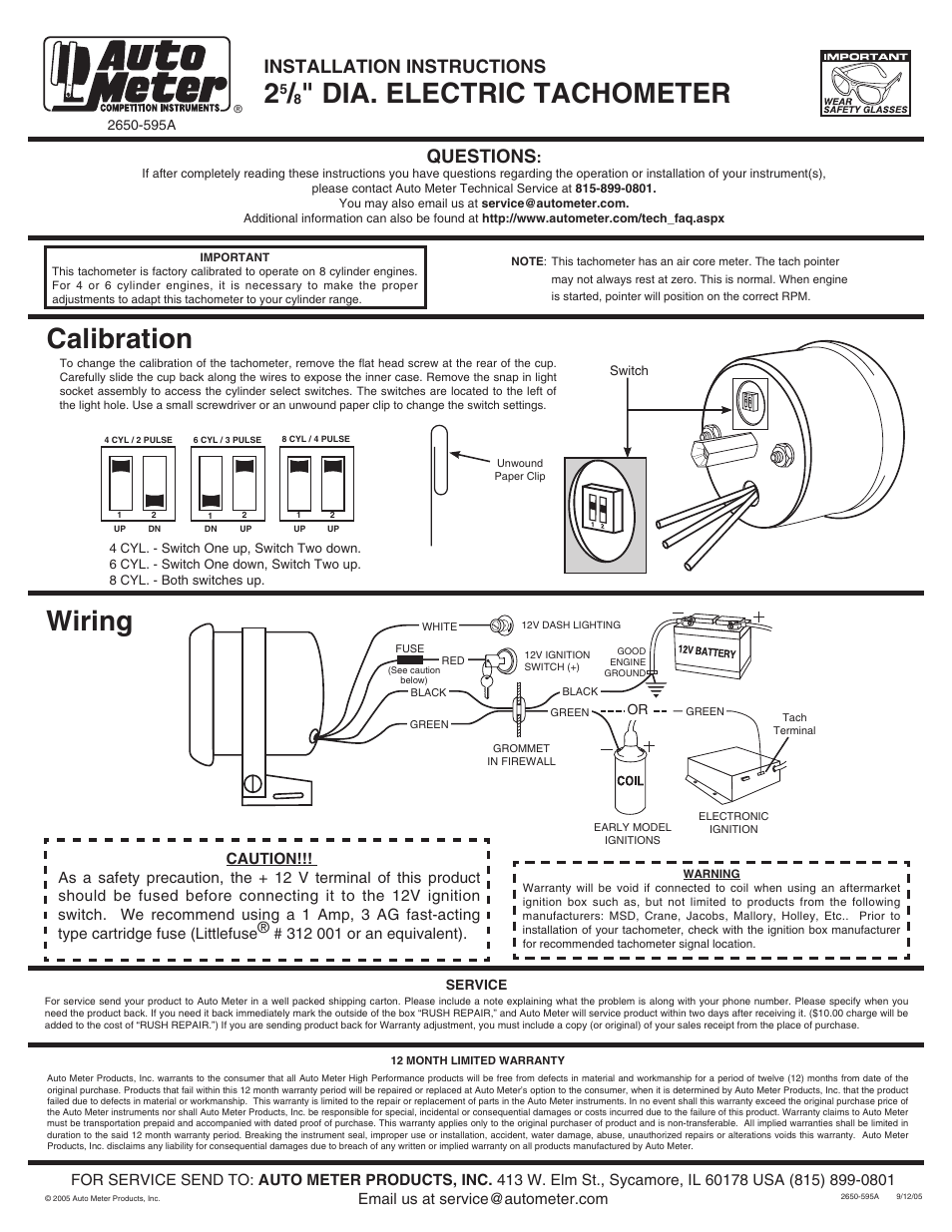
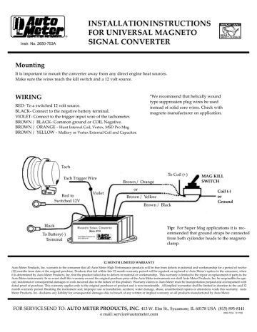
Autometer Gauge Wiring Diagram - auto meter gas gauge wiring diagram, autometer amp gauge wiring diagram, autometer boost gauge wiring diagram, Every electric structure consists of various unique pieces. Each part should be placed and linked to other parts in specific manner. Otherwise, the structure won't work as it should be. Be careful not to touch ignition wire to the sender terminal on back of gauge or the sender will be damaged. CAUTION: INSTALLATION INSTRUCTIONS. 21/16" eLeCTRIC ...2 pages
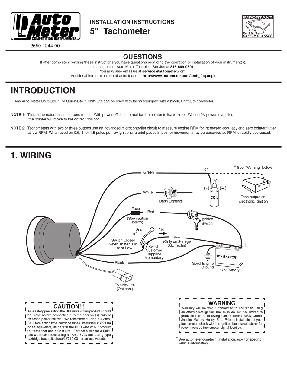
The wiring diagram shows installation on vehicles with original equipment ignitions. If your car is equipped with a specialty aftermarket ignition, ...2 pages
Auto meter wire diagram
Autometer gps speedometer wiring diagram auto meter diesel tach wiring diagram wire center u2022 rh. As stated earlier the lines in a Autometer Tach Wiring Diagram represents wires. Autometer Tachometer Wiring Diagram wiring diagram is a simplified gratifying pictorial representation of an electrical circuit. [http://www.wrxinfo.com/service\_manuals/](http://www.wrxinfo.com/service_manuals/) Been researching some torque specs for suspension stuff and was surprised about the amount of misinformation and confusion out there across forums and videos. Here ya'll go, hope this helps some of you DIYers. Recommended - Auto Meter Hall effect sender, 3-wire 16 pulses/revolution. 5291 Standard 7/8 - 18 thread 5292 Ford, plug in Mounting 1. 8Mount speedometer in a 33/ " dia. hole. Be careful not to cut the hole too large. 2. 8Cut a 3/ " dia. hole in the firewall for the speedometer wires. Place a rubber grommet in the hole and route
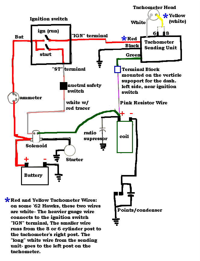
Auto meter wire diagram. Autometer Tach Wiring Diagram - autometer diesel tach wiring diagram, autometer phantom tach wiring diagram, autometer playback tach wiring diagram, Every electrical structure is composed of various diverse parts. Each component ought to be set and linked to different parts in particular way. If not, the structure won't work as it ought to be. If after completely reading these instructions you have questions regarding the operation or installation of your instrument(s), please contact Auto Meter ... auto meter wiring diagram - What's Wiring Diagram? A wiring diagram is a kind of schematic which uses abstract pictorial symbols showing every one of the interconnections of components inside a system. Autometer Pro Comp Ultra Lite Wiring Diagram Fresh Auto Meter Wiring - Autometer Gauge Wiring Diagram. Wiring Diagram arrives with several easy to follow Wiring Diagram Guidelines. It's intended to aid all the average person in developing a suitable method. These guidelines will be easy to understand and apply.
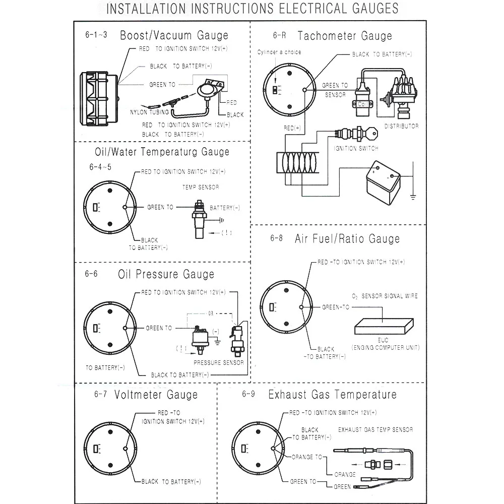
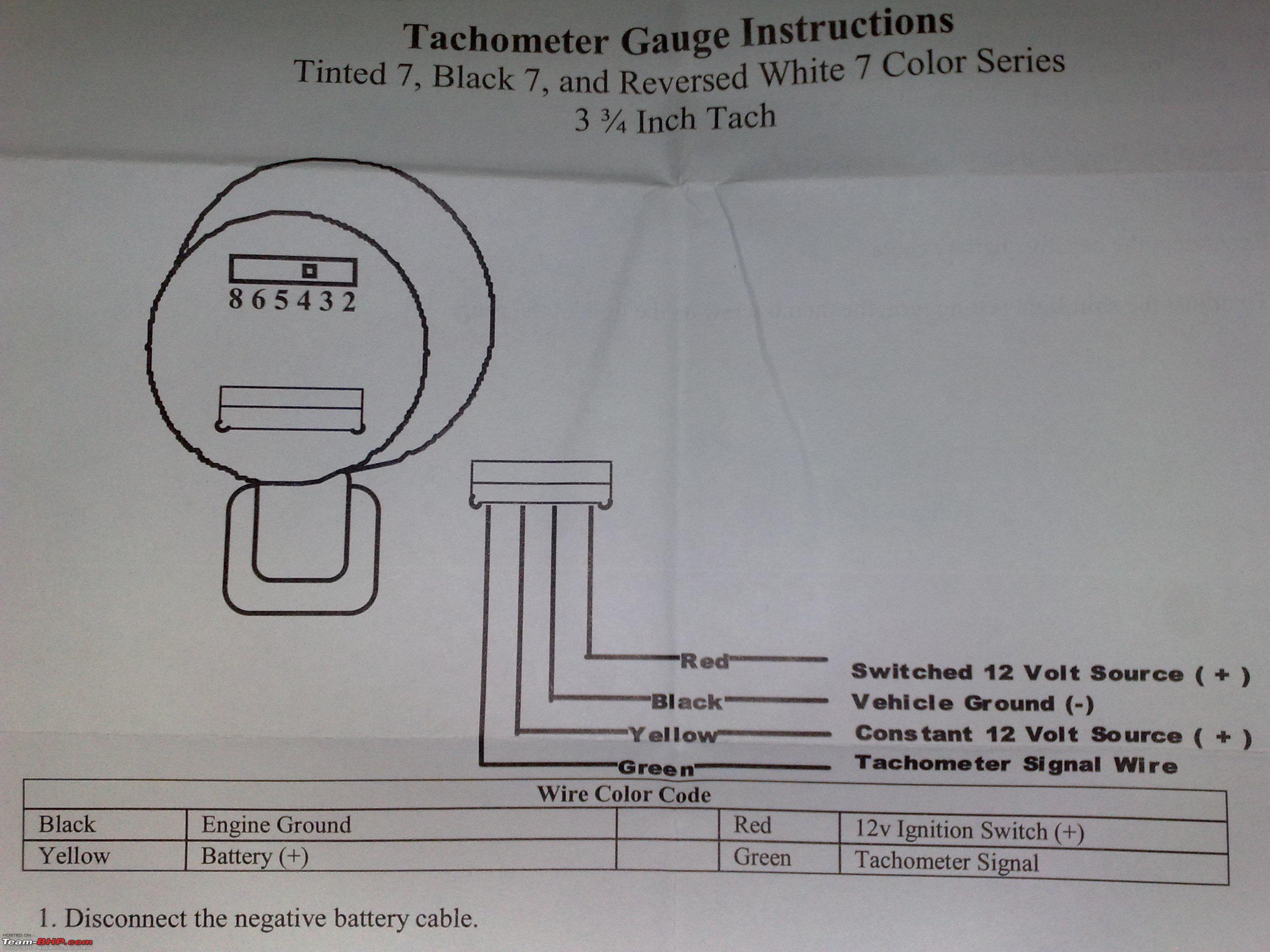
Wiring your new Autometer tachometer into your car will complete the installation. Once you have selected a mounting location, you can run the four wires that operate the tachometer. The tachometer is designed to show the engine RPMs or rotations per minute. Autometer has designed their tach to be used with four, six ... For turbo engines, install the probe inches from the turbo exhaust outlet or . a hole in the dash, a gauge panel or an Auto Meter Gauge Pod.Sep 30, · Need help wiring Autometer electric gauges Posted by blcknspo0ln, Sep 17, Sep 17, #1. blcknspo0ln The actual diagram can be found in the DSM manual or something like a Haynes manual. Auto Meter Products. 413 W Elm St. Sycamore, IL 60178. Toll Free Tech Support: 866.248.6357. Toll Free Customer Service: 866.248.6356. International: 815.895.8141 A wiring diagram is a simplified conventional photographic representation of an electrical circuit. 8mount speedometer in a 33 dia. The electronic speedometer in this instrument is designed to operate with an electrical speed sender. W auto meter gps interface. Place a rubber grommet in the hole and route.
Autometer voltmeter wiring diagram. Voltmeter wiring figure 5. Voltmeter wiring figure 5. Voltmeter instructions wire nut flat washer nut washer voltmeter grommet u bracket do not leave any hardware out of these connections diagram 1 ground source step 2 should be connected as shown in diagram 1 to the voltmeter s connection post marked. 1 16 ... The folks at Autometer put together a couple quick videos explaining what wire goes where. CAUTION FOR ALL GAUGE INSTALLATION. As a safety precaution, the 12V wire attached to the positive I () terminal of the gauge should be fused before. The wiring diagram shown is a typical installation. For Chrysler Blue, Gold and Silver Boxes, Ford Standard Electronic ... Auto Meter Products, Inc. warrants to the consumer that all Auto Meter High Performance products will be free from defects in material and workmanship for a period of twelve (12) months from date of the ... Aug 15, · Autometer Pyrometer Wiring Diagram auto meter ficial site trade in any aftermarket gauges for credit on new autometer gauges 15 trade in trade up read more auto Autometer Pyrometer Wiring Diagram Isspro Electric Water Temp img source: diagramweb.net Autometer Pyrometer Wiring Diagram As Well As Temperature Gauge img source.
AUTO METER 6858 INSTALLATION INSTRUCTIONS Pdf Download ...
Autometer tach wiring diagram. For chrysler blue gold and silver. The wiring diagram shown is a typical installation. Figure a figure c. A wiring diagram is a simplified traditional pictorial depiction of an electrical circuit. The tach must be returned to autometer for a light replacement. Toll free tech support.

5" inch 4 in1 Auto Tachometer RPM Meter with Shift Light ...
Autometer Tach Wiring Diagram Auto Meter Sport P Electrical Drawing Rh G News Co on random diagrams, auto meter monster tach wiring diagram diagrams.A tachometer is a good addition to any vehicle equipped with a manual transmission. In my Jeep CJ-7, I didn't have one of those rare factory tachs so I chose the Autogage Tachometer /4 inch with an ...

Download Vehicle Wiring Diagram Free for Android - Vehicle ...
STEP 4. Run a length of wire from the temperature gauge to the sender unit using the wire supplied with the kit. Bare 1/4" of the end of the wire supplied at the sender unit. Install an eyelet terminal supplied with the kit on the end of the wire and crimp it tightly with a pair .Autometer Egt Wiring Diagram | Wiring LibraryAutometer Oil ...

Autometer gauges - MK2 MR2 and 1MZ V6 with COPS | MR2 Owners ...
Pictured below is a copy of the wiring diagram for the Autometer Oil Pressure Gauge. To install an oil pressure gauge you will first need to purchase one. Pictured below is a copy of the wiring diagram for the Autometer Oil Pressure Gauge. left is labeled 'S', signal wire from oil pressure or water temp sensor? .
52mm Dual Display Car Meter 7 Colors Led Air Fuel Ratio Gauge ...
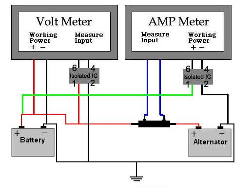
wire to the left connection post as shown in Diagram 2. Do not over tighten. 7. Connect one end of another length of 18-gauge insulated copper wire to the center connection post, as shown in Diagram 2 and the other end of the wire to a good ground source. 8. Connect a third length of 18-gauge insulated copper wire to the right connection post as

How do I hook up a Autometer Tach to my 2003 Chevy Cavaleir ...
How to Install an Auto Meter Pro-Comp Ultra-Lite Water Temp Gauge - Electric on Your Musta double check that all connections are tight. After starting engine, check wiring connections for hot spots. Be prepared to shut engine off immediately if hot spots are detected.
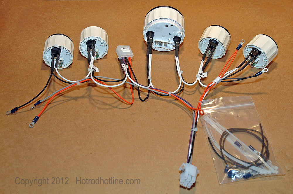
Updating To An Electrical Gauge Package | Hotrod Hotline
Autometer Basic Tach Installation Wiring Instructions Tutorial How-To http://www.jegs.com/webapp/wcs/stores/servlet/KeywordSearchCmd?manufacturer=Auto%20Mete...
temperature displays - Page 8
Recommended - Auto Meter Hall effect sender, 3-wire 16 pulses/revolution. Standard 7/8 - 18 thread 5292 Ford, plug in GPS Interface Module Universal Speed Sensor 3299 Optional Tach/Speedo Gauge Connector ... Wiring - Diagram 1 SIG Engine Dash Lighting Ground GND +12V GND LAMP OUT
How To Install a Tachometer
Wiring diagram for auto meter new wiring diagram auto gauge a newbie s overview of circuit diagrams. Toll free tech support. Pin On Gauges . Higginbotham fuel gauge wiring diagram rate fuel gauge wiring autometer gauge wiring diagram additionally wiring diagram provides you with enough time frame by which the assignments are to be accomplished.
Installing Auto Meter Fuel Pressure Gauge With Racepak USM ...
Autometer Sport Comp Tach Wiring Diagram. Wiring. The special design of the tachometer base allows for a variety of mounting For service send your product to Auto Meter in a well packed shipping carton. To operate the Sport-Comp Shift-Lite tachometer, first determine your desired. Sport-Comp Playback Tachometer · DPSS Shift-Light - Level 2 or ...
How to Install Auto Meter Programmable Speedometer Gauge - 0 ...
Connect this to the signal wire at your speed sender/sensor. If you are using a computer (ECM, PCM, ECU, etc), you may connect this to the factory speed signal wire at the computer instead of the speed sensor if it is equipped. Consult a diagram for your computer to verify. Blue: Oil PSI sender wire. Connect this to the Auto Meter oil pressure ...
Tachometers - Page 15 - Team-BHP
Does anyone know where I can find free or cheap wiring diagrams, specifically for an 03 Dodge Caravan 3.3L? Have a no-start issue, everything seems to point to the ECM has gone bad, but to fully rule everything else out I need the wiring diagrams.
DRAGON GAUGE 2"52mm 12V Turbo Boost Gauge -1~2bar Black Turbo ...
Autometer Sport Comp Tach Wiring Diagram. As a safety precaution the RED wire of this product should be fused before connecting it to the positive (+) side of switched power source. We recommend using. Any Auto Meter Shift-Lite™, or Quick-Lite™ Shift-Lite can be used with tachs 2) Pass tach wires through shock strap assembly and slide tach ...
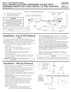
Fillable Online fULL Sweep eLeCTRIC pReSSURe gAUge wITh ...
I really need to know the pinout (numbers) for the 2010 stereo harness. I have searched for about 3 1/2 hours and come up with absolutely nothing. I have a 2008 mustang that I am putting a 2010 steering wheel on, and am wiring up the controls for volume / track via a SWC module. I need to know what pins 18 and 19 are on the 2010 mustang, and which pins those would be on the 2008 mustang. any help at all would be appreciated more than you know!

AutoMeter 5893 Phantom In-Dash Mechanical Speedometer ...
The wiring diagram shown is a typical installation. Figure A ... the light should ever fail, the tach must be returned to AutoMeter for a light replacement.2 pages

auto gauge tachometer wiring diagram, auto gauge tachometer ...
Autometer Pro Comp Ultra Lite Wiring Diagram Fresh Auto Meter Wiring - Autometer Gauge Wiring Diagram. Wiring Diagram arrives with several easy to follow Wiring Diagram Guidelines. It's intended to aid all the average person in developing a suitable method. These guidelines will be easy to understand and apply.

AUTO METER 9118 Tachometer Magneto Signal Converter
Hey all, I saw [u/apgadoz's Super Duper Prophecy](https://www.youtube.com/watch?v=jtPZSjWzn70), and I was wondering if anyone had a wiring diagram that was similar to the way he had his Prophecy wired. I could somewhat make out what the wiring looked like, but I'm still confused as to how it's wired. I know that there was a PWM and a MOSFET \[both of which I already have\]. Any help is appreciated.

Gauge Wiring Harness/Mechanical Speedometer | Painless ...
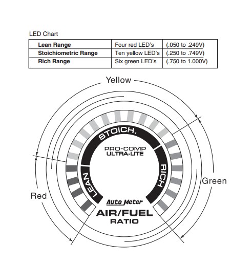
Autometer Boost Gauge Wiring Diagram. How to Install an Auto Meter Pro-Comp Ultra-Lite Air/Fuel Ratio Gauge - Electric on Your M or wiring diagram for your specific vehicle to learn which wire is the signal. WARNING. Do not connect ohm meter to oxygen sensor, or touch wire to ground or power. Damage to oxygen sensor will result. diagramweb.net ...

Wiring diagram Electrical Wires & Cable Fuse Class diagram ...
White Wire: Connect to +12 Volt Lighting. INSTALLATION INSTRUCTIONS. SHORT SWEEP ELECTRIC GAUGES. 2650-1079-00 Rev. C. Mounting. Replace light bulb with the same . number bulb as the one removed. These gauges can be mounted in-dash or in Auto Meter mounting solutions (panels, cups, pods, etc.). 2. 1 ⁄ 16" diameter gauges mount in 2. 1 ⁄ 16 ...
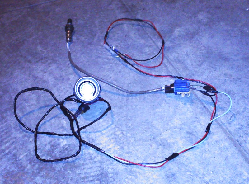
How-to: Tuning Carbs with an Oxygen Sensor and A/F Gauge ...
Recommended - Auto Meter Hall effect sender, 3-wire 16 pulses/revolution. 5291 Standard 7/8 - 18 thread 5292 Ford, plug in Mounting 1. 8Mount speedometer in a 33/ " dia. hole. Be careful not to cut the hole too large. 2. 8Cut a 3/ " dia. hole in the firewall for the speedometer wires. Place a rubber grommet in the hole and route
Autometer 19466 Speedo/Tach combo install - just say no ...
[http://www.wrxinfo.com/service\_manuals/](http://www.wrxinfo.com/service_manuals/) Been researching some torque specs for suspension stuff and was surprised about the amount of misinformation and confusion out there across forums and videos. Here ya'll go, hope this helps some of you DIYers.

TAKE IT IN TOP!: Wiring Diagram for Smiths Classic Gauges
Autometer gps speedometer wiring diagram auto meter diesel tach wiring diagram wire center u2022 rh. As stated earlier the lines in a Autometer Tach Wiring Diagram represents wires. Autometer Tachometer Wiring Diagram wiring diagram is a simplified gratifying pictorial representation of an electrical circuit.

MH TERAJU INDAH: Auto Car Meter Fuel Gauge proton wira,iswara ...

MH TERAJU INDAH: Auto Car Meter Fuel Gauge proton wira,iswara ...
Explanation of Voltage and Current Input Wiring Diagram for ...
Installation

Morgan +4, 4/4, +8, Aero 8 Car Wiring Diagrams | morgan ...

Air/Fuel Ratio Gauge
Official Website of the BCOIE Chapter
Autometer EGT pyrometer gauge intall tap size (pic) - RX7Club ...

Amazon.com: Auto Meter 5252 25' Wire Harness (Extension ...

Auto Gauge Schematic | PDF | Ignition System | Components
Auto Meter 2893 User Manual | 1 page | Also for: 2891, 2892, 2890

Auto Meter Electronic Speedometer Sending Unit (GM) Through drive for cruise control.
Auto Meter Programmable Electric Speedometer
Installing Auto Meter Fuel Pressure Gauge With Racepak USM ...

EFRL owner club - diagram meter myvi 1. hijau cair - IG ...
Auto Meter 9118 Tachometer Signal Pickup Installation ...
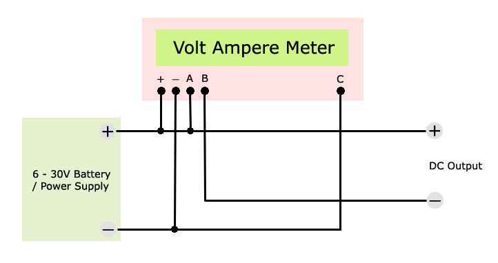
Voltmeter Ammeter
CHEVROLET - Car PDF Manual, Wiring Diagram & Fault Codes DTC
Installation Instructions for Auto Meter Cobalt Air/Fuel ...

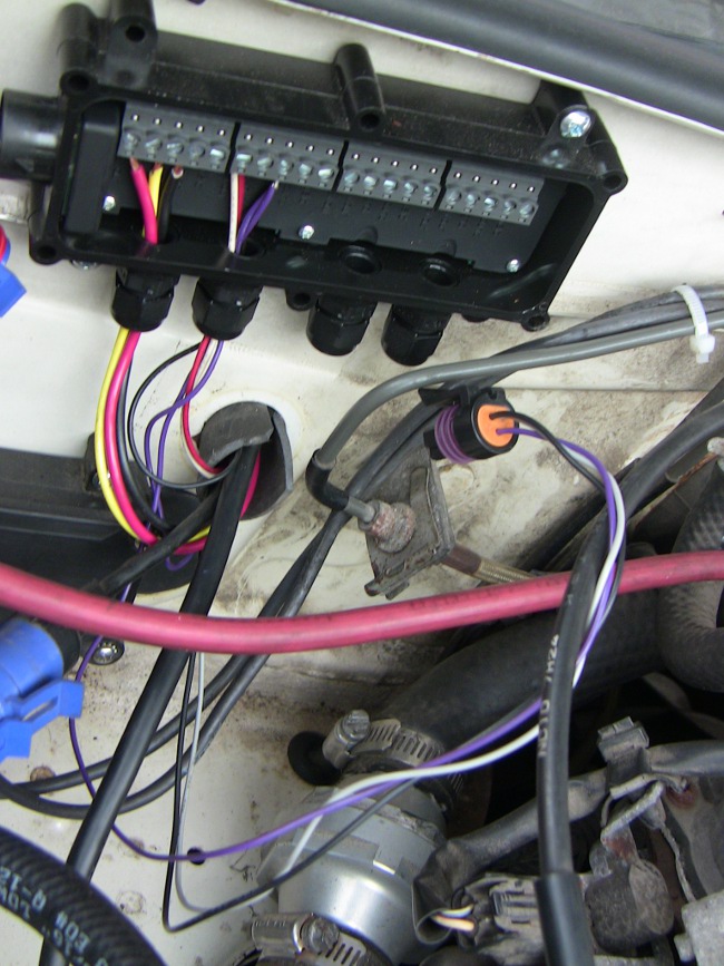
Wiring Up A 5'' Monster Tacho In Your Car - Car Electrical ...

AUT4319 Autometer 4319 Ultra-Lite Fuel Level Gauge, 2-1/16 ...


Comments
Post a Comment