40 2 wire alternator wiring diagram
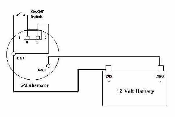
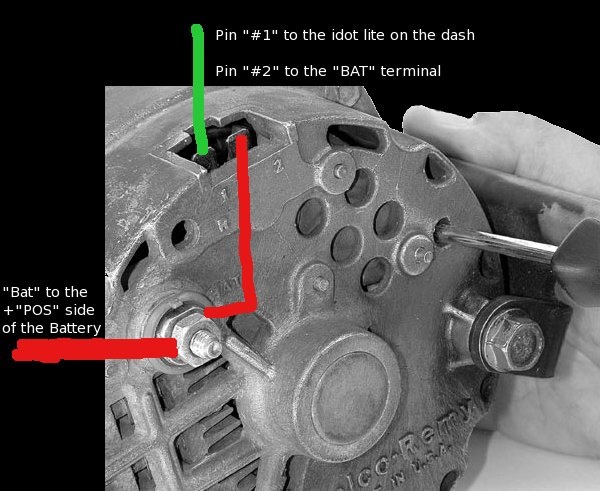
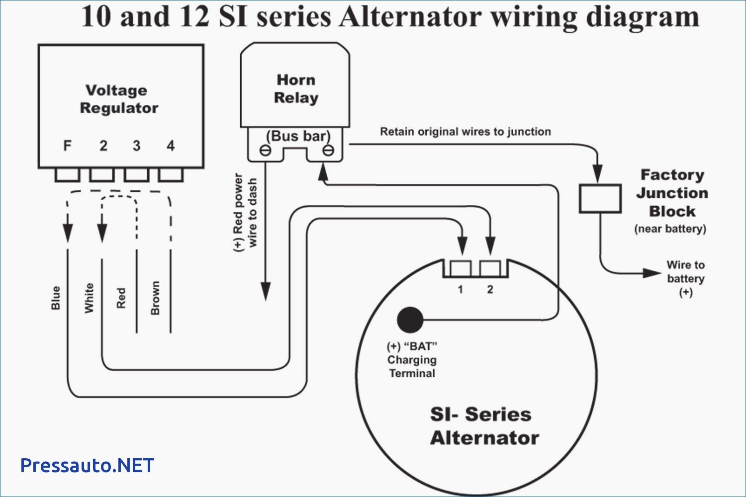
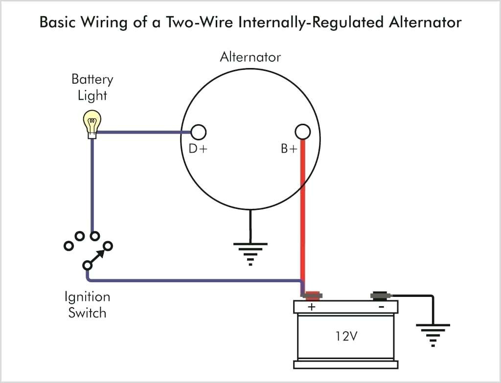
Need a wiring diagram for a bosch alternator. If you ask for a one wire delco alternator,all you have to do is connect the large wire on back of the alternator to the positive battery post on the battery.The alternator is self energizing,there for no problem with wiring up a harness.If I can help,let me know my name is Ron.>>> roniecon@gmail.com. If the voltage rises above or falls below 12 Volts, the alternator's internal voltage increases or reduces power output to maintain 12 Volts to the battery and the systems of the vehicle during operation. The second wire of the pair on Pin 2 of the alternator goes to the ignition.
2 wire alternator wiring diagram - You will need a comprehensive, skilled, and easy to know Wiring Diagram. With this kind of an illustrative guidebook, you are going to be able to troubleshoot, prevent, and total your projects without difficulty.

2 wire alternator wiring diagram
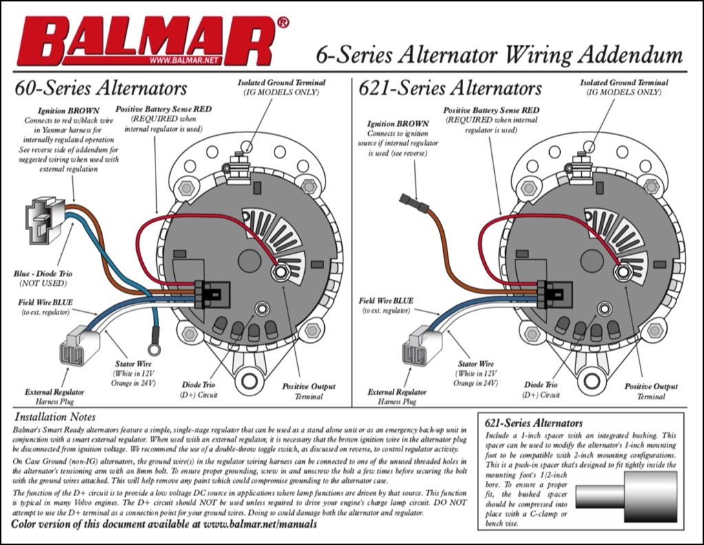
Installation: Follow diagrams. *For use with Locate and remove the plug-in connector from the alternator. 2. Now connect the red wire from the plug-in connector to Battery #1 outer post of the isolator using the ring terminal. 6. Connect the output cable (see cable sizing recommendations below) ground, field wire, stator (tach) wire if needed and other necessary wiring. Connect alternator to Balmar regulator wiring harness as indicated in wiring diagram included on Page 12. The alternator's positive and ground cables should be sized according to the chart on Page 3. 2 wire alternator wiring diagram - You will need a comprehensive, skilled, and easy to know Wiring Diagram. With this kind of an illustrative guidebook, you are going to be able to troubleshoot, prevent, and total your projects without difficulty.
2 wire alternator wiring diagram. How to connect 2 wire Delco 10si and CS130 alternators using charge connector plugs. This is a three-wire alternating wiring diagram showing the connections between the different components of a circuit. It is meant to aid all of the average person in building a correct system. This particular model 10SI used in. 10si Alternator Wiring Diagram. As stated previous, the traces at a 2 Wire Alternator Wiring Diagram signifies wires. Occasionally, the wires will cross. However, it does not mean link between the cables. Injunction of two wires is usually indicated by black dot at the intersection of two lines. There will be primary lines that are represented by L1, L2, L3, and so on. Two Wire Alternator Wiring Diagram. Print the cabling diagram off in addition to use highlighters to trace the circuit. When you employ your finger or even the actual circuit along with your eyes, it's easy to mistrace the circuit. One trick that We use is to print exactly the same wiring picture off twice. Denso 2 Wire Alternator Wiring Diagram from static-assets.imageservice.cloud. Print the cabling diagram off plus use highlighters in order to trace the routine. When you make use of your finger or even follow the circuit together with your eyes, it is easy to mistrace the circuit. 1 trick that We 2 to printing the same wiring plan off twice.
Powermaster Alternator Wiring Diagram. P/N. Chrysler Alternators. Instruction Sheet. Chrome Chrysler Alternator w /Double Grv. Pul. 75 Amp. Chrome Chrysler One Wire Alternator. NEVER disconnect a battery cable or alternator cable and wires when In many cases the OE pulley can be reused on the Powermaster alternator if necessary. Kindly please help me with a complete wiring diagram for Alfa Romeo 155v6 2.5 167(AIC)..1995 to show the Bosch Motronic 88 pin outs and the location on the car of the ignition COTROL module.Thanks a mil and Happy New Year from Nairobi. #426. Paul Finney (Thursday, 06 January 2022 12:48) Gm Alt Wiring | Wiring Diagram - 2 Wire Alternator Wiring Diagram Wiring Diagram includes many comprehensive illustrations that present the relationship of various products. It contains directions and diagrams for various varieties of wiring techniques as well as other products like lights, windows, and so forth. Common Delco SI Series Alternator Wiring Diagram. by David Smith Sep 22, 2016. We are commonly asked how to wire the Delco SI series alternators upon maintenance or upgrading from an older generator. While this series of unit often runs as a self exciting one wire, agricultural applications also used 3 wire connections to the alternator.
The two wires in an alternator is for 1 is for key ON mains which receives the battery power through the ECM and conducts through the regulator and returns ...3 answers · 3 votes: If the alternator has only two wires then one will be quite thicker than the other one and that ... According to earlier, the lines in a 2 Wire Alternator Wiring Diagram signifies wires. Occasionally, the cables will cross. But, it doesn't mean connection between the wires. Injunction of two wires is generally indicated by black dot to the junction of 2 lines. There will be principal lines which are represented by L1, L2, L3, and so on. 2 Alternator Basic wiring diagram. 21 Exciter wire Battery light Key Switch To Battery As mentioned before we need the correct voltage at the alternator for it to operate properly. This voltage down the exciter wire to the alternator. Oct 24, · gahi's diagram is the correct way to wire a GM 10SI/12SI, and utilize all the benefits of that great ... Kindly please help me with a complete wiring diagram for Alfa Romeo 155v6 2.5 167(AIC)..1995 to show the Bosch Motronic 88 pin outs and the location on the car of the ignition COTROL module.Thanks a mil and Happy New Year from Nairobi. #426. Paul Finney (Thursday, 06 January 2022 12:48)
How to Re-Wire Your Car (Replacing the Wiring Harness): Part 1
Balmar alternator wiring diagram schematics wiring diagram 2 wire alternator wiring diagram. Alternator-Upgrade Wiring Tips For Popular GM Charging Systems. Alternator upgrade wiring tips for popular gm charging systems 2020 02 19 18 19 21 873740.

Monochrome, Power Lines, Winlaton Mill, Tyne & Wear, England.
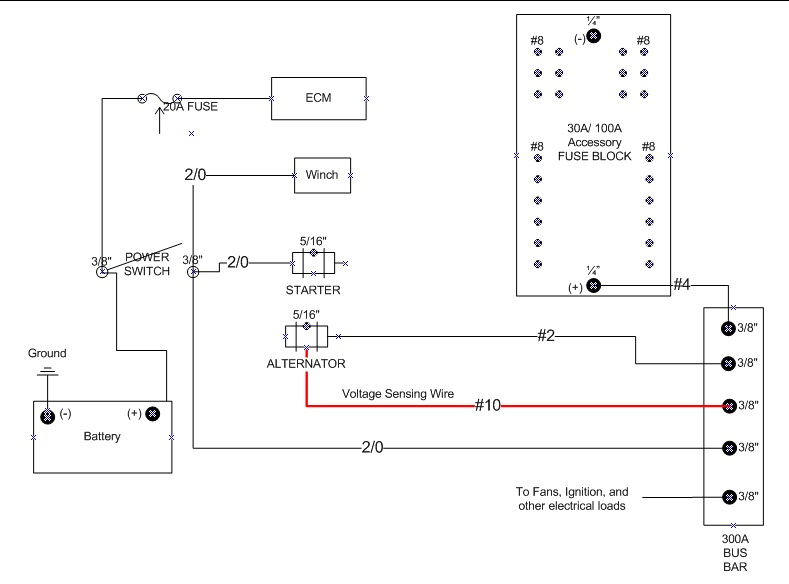
This is a three-wire alternating wiring diagram showing the connections between the different components of a circuit. The circuit comprises three main wires: battery positive cable, voltage sensing wire, and ignition wire. The ignition input wire is attached to the engine. It conducts electricity from the engine to the alternator while the ...

Wiring Diagram Vw Alternator
A typical 3-wire alternator wiring diagram with an internal voltage regulator. Computer-Controlled Voltage Regulation. Many late-model vehicles use the engine computer, which is often referred to as the powertrain control module (PCM), to control alternator output. Most modules use an internal driver to turn the alternator's field circuit on ...
Gm 2 Wire Alternator Wiring Diagram - Visual Diagram
In this wiring diagram, the builtin switch is controlled by separate source (i.e. wires from different CB) while the outlet is connected to the second source. To do this, simple remove the breakaway fin between the line terminals and connect the upper terminal to source one and the lower line terminal to source two.

Alternator Wiring Diagram With Voltage Regulator ...
How do I wire my marine alternator? Many alternators require ignition voltage to initiate charging. You must verify that all required connections are connected to the proper terminal and have the correct voltage in order for the alternator to operate properly. Below you will find the most common alternator circuits used on marine applications.

Bosch 2 Wire Alternator Wiring Diagram Collection
Charging System & Wiring DiagramAmazon Printed Bookshttps://www.createspace.com/3623931Amazon Kindle Editionhttp://www.amazon.com/Automotive-Electronic-Diagn...

Wiring Diagram Info: 31 2 Wire Alternator Wiring Diagram
2 wire alternator wiring diagram. Battery positive cable voltage sensing wire and ignition wire. Alternators Renault 19 Ii 1 8 110cc Petrol Engine. This is a three-wire alternating wiring diagram showing the connections between the different components of a circuit.

Delco Remy 2 Wire Alternator Wiring Diagram - Technology Now
Hot Rod Wiring - Diagram Please Note: This diagram was designed for 12 volt systems, but can also be used for 6 volt systems. If used for 6 volt, make all the wires heavier by 2 gauges. For example 14 gauge wire will become 12 gauge, 10 gauge will be 8 gauge, etc.

Wiring Diagram For Alternator With External Regulator
gahi's diagram is the correct way to wire a GM 10SI/12SI, and utilize all the benefits of that great design. The output and sensor wire (#2) should go to the main power distribution location, as shown, not to the battery. The #2 wire ensures the 14.4 or so output is fed to the entire system, eliminating any voltage drop.

Alternator wiring - diagnosis? - LS1TECH - Camaro and ...
Gm Alt Wiring | Wiring Diagram - 2 Wire Alternator Wiring Diagram Wiring Diagram includes many comprehensive illustrations that present the relationship of various products. It contains directions and diagrams for various varieties of wiring techniques as well as other products like lights, windows, and so forth.

Pin on Superior Automotive Technicians' Cars
Answer (1 of 3): If the alternator has only two wires then one will be quite thicker than the other one and that will be the wire between the battery positive and the alternator that carries the charging current, the thinner wire will be the connection to the warning lamp that also serves as the ...

Denso 40A Compact Alternator - Page 2 - Tech Talk - WSCC ...
This is the symbol associated with a relay in wiring diagrams. How to wire a relay? ... The diagram above is the 5 pin relay wiring diagram. There are different kinds of relays for different purposes. ... A Complete Tutorial Cat5 Wiring Diagram: A Complete Tutorial Alternator Wiring Diagram: A Complete Tutorial 3 Way Switch Wiring Diagram: A ...

Delco 2 Wire Alternator Wiring Diagram Collection
2 Wire Alternator Wiring Diagram from www.2carpros.com Print the cabling diagram off plus use highlighters to be able to trace the signal. When you make use of your finger or the actual circuit along with your eyes, it may be easy to mistrace the circuit. One trick that We use is to print the same wiring picture off twice.
1 wire alternator conversion - Page 2 - Ford Truck ...
Bosch 2 Wire Alternator Wiring Diagram Source: discourse-cdn.jag-lovers.com READ Pioneer Deh 2700 Wiring Diagram Collection Read wiring diagrams from negative to positive in addition to redraw the signal being a straight line.

55 Gm 2 Wire Alternator Wiring - Wiring Diagram Harness
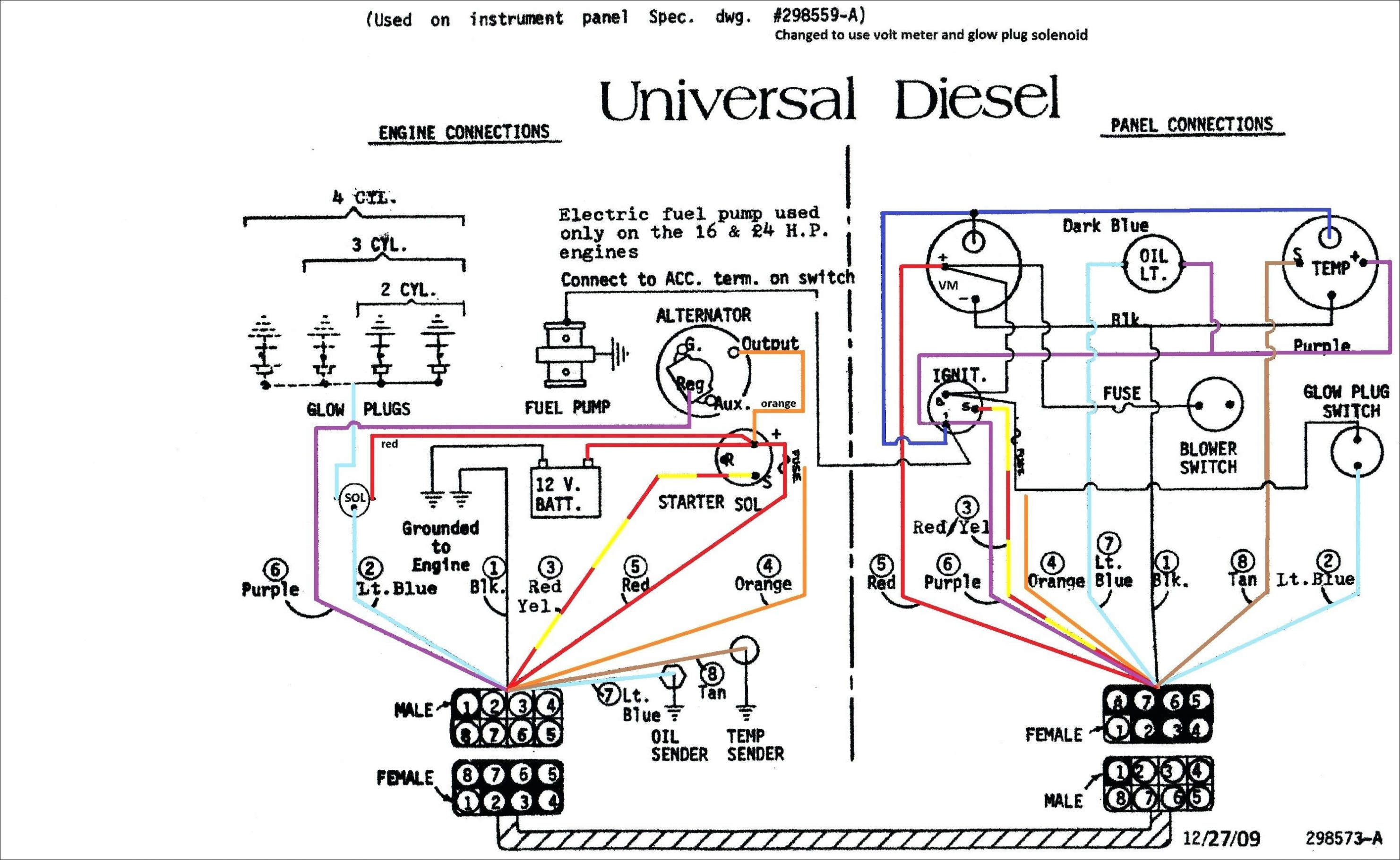
LIGHT BLUE: It is used to wire oil pressure lenders to the gauge. TAN: It is used to wire the water temperature to the sender gauge. ORANGE: Its is used for there types of boat wiring i.e it is used to 1) wire distribution panels to accessory switches, 2) Ammeter to alternator and generator output, 3) boat accessory fuses or switches.

Alternator Wiring Diagram 2 Wire For Your Needs
12/01/2015 · Kindly please help me with a complete wiring diagram for Alfa Romeo 155v6 2.5 167(AIC)..1995 to show the Bosch Motronic 88 pin outs and the location on the car of the ignition COTROL module.Thanks a mil and Happy New Year from Nairobi. #426. Paul Finney (Thursday, 06 January 2022 12:48)

dual alternator battery isolator wiring diagram ...
Denso 2 Wire Alternator Wiring Diagram from static-assetsimageservicecloud. Step 3 Remove the 2 wires from the generator these 2 leads go to the old voltage regulator. Jul 19 2-unbolt the 10mm nut for the wire at the battery fuse panel cut the zip ties along the way and pull the cable out of its brackets.

2 Wire Alternator Wiring Diagram
Note: the alternator charge wire routes direct to the battery and not through any switch connection, the alternator will not operate correctly if not connected direct to battery or directly through the ammeter. Note: the wiring that comes with our kits should be used as it is sized to handle the amperage.

'66 Alternator Wiring - Is this Right? - Vintage Mustang ...
2 wire alternator wiring diagram - You will need a comprehensive, skilled, and easy to know Wiring Diagram. With this kind of an illustrative guidebook, you are going to be able to troubleshoot, prevent, and total your projects without difficulty.
55 Gm 2 Wire Alternator Wiring - Wiring Diagram Harness
6. Connect the output cable (see cable sizing recommendations below) ground, field wire, stator (tach) wire if needed and other necessary wiring. Connect alternator to Balmar regulator wiring harness as indicated in wiring diagram included on Page 12. The alternator's positive and ground cables should be sized according to the chart on Page 3.
58 2 Wire Alternator Hook Up - Wiring Diagram Harness
Installation: Follow diagrams. *For use with Locate and remove the plug-in connector from the alternator. 2. Now connect the red wire from the plug-in connector to Battery #1 outer post of the isolator using the ring terminal.

dual alternator battery isolator wiring diagram ...

Wiring Diagram For A Gm 3 Wire Alternator - Database ...
10SI and 12SI Alternator wiring issue discovered - El ...

Delco Remy 2 Wire Alternator Wiring Diagram - Technology Now

Delco Alternator Conversion - Page 3

How to Re-Wire Your Car (Replacing the Wiring Harness): Part 1

ins:billow926
2 Wire Alternator Wiring Diagram - Database | Wiring ...
Gm Alt Wiring | Wiring Diagram - 2 Wire Alternator Wiring ...

Voltage Regulator (int.) / How it works | IH8MUD Forum

Fleetmatics Wiring Diagram
Gm 2 Wire Alternator Wiring Diagram | Wiring Diagram
2 Wire Alternator Wiring Diagram | Wiring Diagram

Incredible and I think tallest Gondola in the world. For size reference that little gondola you see sits about 16 people so they are huge.

» GM CS130/CS144 Alternator Wiring - (PLFS) 2-Wire - GM ...

ins:billow926
2 Wire Alternator Wiring Diagram | Wiring Diagram

2 Wire Alternator Diagram - SKEMASKALA

Denso 2 Wire Alternator Wiring Diagram Database


Comments
Post a Comment