39 shunt trip wiring diagram
A Shunt trip wiring diagram as your wiring guide; Insulating gloves and eye protection; Not all circuit breakers accept shunt trip accessories. In fact, different breakers may require specific shunt trip accessory models. Some breakers also have a built-in shunt trip accessory—all you need is to wire and connect to your circuit to activate it. Pigtail. Diagram. CHST Eaton Cutler-Hammer 1P 20A Shunt Trip Breaker. Type CH 3/4-Inch Standard Circuit Breaker, Single-Pole, 20A, /V, 10 Kaic, (1) # The Shunt Trip allows a circuit breaker to be tripped remotely by applying a voltage to the wire leads. The unit Figure Shunt Trip Connection Diagram. Instruction Leaflet IL 29CG.
shunt breaker wiring diagram – What is a Wiring Diagram? A wiring diagram is a simple visual representation in the physical connections and physical layout associated with an electrical system or circuit. It shows how the electrical wires are interconnected and will also show where fixtures and components may be coupled to the system.

Shunt trip wiring diagram
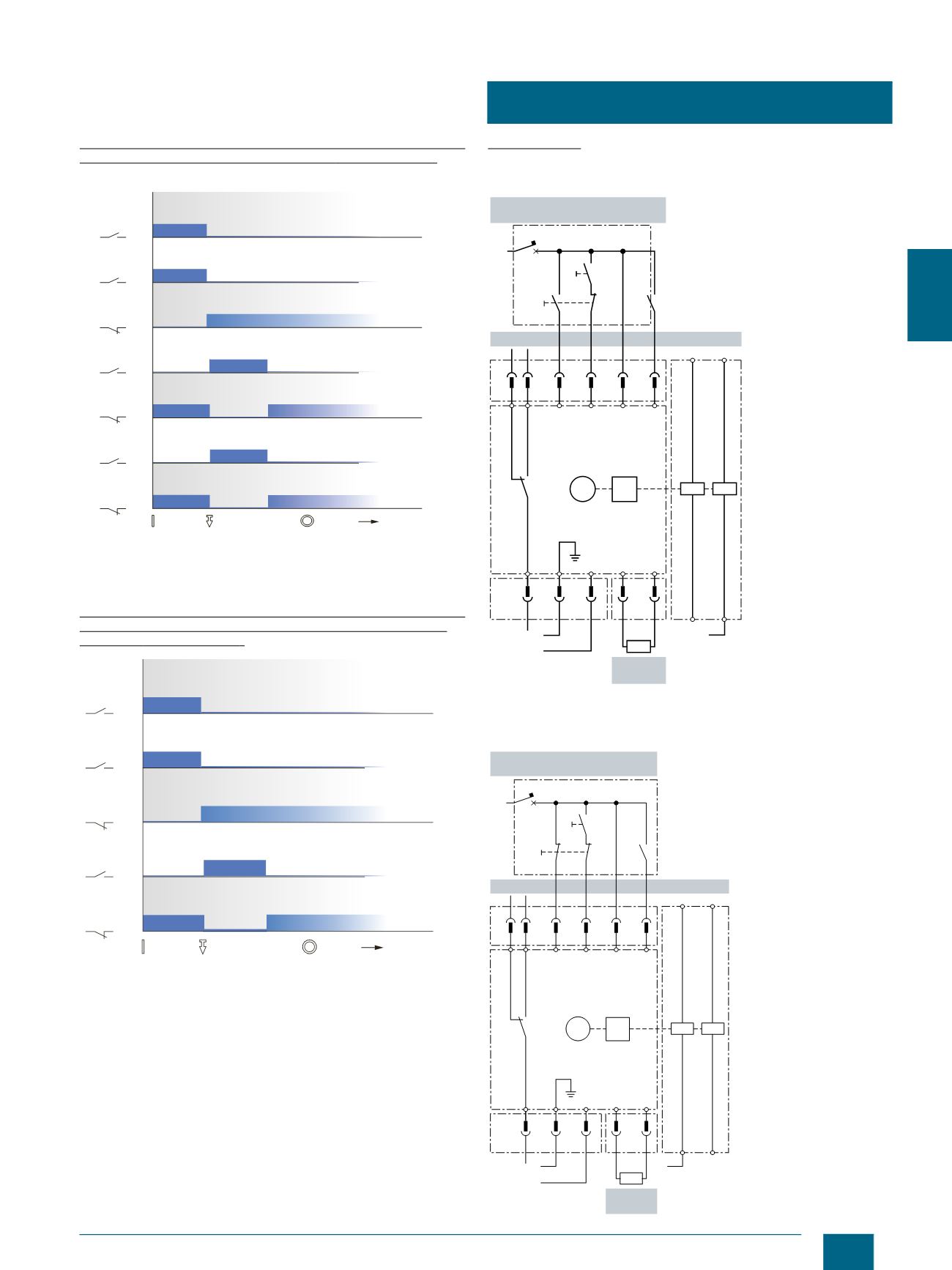
Shunt trip breaker wiring diagram. How it works the electrical current in a building passes through the system s circuit breaker unchanged if the current remains below a specified limit. It shows the elements of the circuit as simplified shapes as well as the power as well as signal connections in between the gadgets. As stated previous, the lines in a Shunt Trip Breaker Wiring Diagramsignifies wires. Occasionally, the wires will cross. However, it doesn’t imply link between the wires. Injunction of 2 wires is generally indicated by black dot on the intersection of two lines. There will be primary lines which are represented by L1, L2, L3, and so on. Shunt trip (MX) When the shunt trip (MX) receives a pulse-type or maintained voltage within specified tolerances it signals the circuit breaker to open. Show QR code for this page. Was this helpful?
Shunt trip wiring diagram. Shunt trip wiring diagram square d. A wiring diagram is a simplified traditional photographic depiction of an electric circuit. Shunt trip wiring diagram square d building electrical wiring representations show the approximate areas and affiliations of receptacles illumination and also long term electric services in a building. Figure 5-1 Shunt Trip removal Apply labels. Figure 3-5 Accessory Identification and Circuit Diagram label application ON TRIP OFF RESET Step 2: After taking all necessary precautions, apply rated voltage to Shunt Trip and ensure the breaker handle moves to the TRIP position. 5 Tutorial for wiring a shunt trip QO™ (and QOB) Circuit Breaker. Shunt trips (accessories) in QO™ breakers are factory installed only and can not be added to ... Shunt Trip (MX) and Undervoltage Trip (MN) A voltage release can be used to trip the circuit breaker using a control signal. Table 81: Shunt Trip and Undervoltage Trip Applications Shunt Trip (MX) • Trips the circuit breaker when the control voltage rises above 70% of its rated voltage • Impulse type 20 ms or maintained control signals
NOTE: A recommended wiring schematic for the communicating style shunt trip or shunt close coils is shown below. Induced voltages in the circuit at terminal C2 and/or A2 can cause the shunt trip or shunt close to not work properly. Square D 120v 20a Single Pole Shunt Trip Breaker Wiring Diagram. V to V for the suffix) to the two terminals on the shunt trip. Land the switch leg from the source contact on one terminal (either) and the neutral wire. Circuit breakers provide a manual means of energizing and Single Pole, V , Takes up space of 2 poles; Shunt trip breaker allows ... Jun 18, 2018 · DOWNLOAD. Wiring Diagram Images Detail: Name: siemens shunt trip breaker wiring diagram – Siemens Shunt Trip Breaker Wiring Diagram Unbelievable Heavenly And. File Type: JPG. Source: techreviewed.org. Size: 737.05 KB. Dimension: 3521 x 2290. DOWNLOAD. Wiring Diagram Pics Detail: Nov 09, 2021 · Shunt trip wiring diagram square d building electrical wiring representations show the approximate areas and affiliations of receptacles illumination and also long term electric services in a building. Wiring Diagram Pics Detail. 120v to 240v for the 1021 suffix to the two terminals on the shunt trip.
In this video i complete explain the shunt trip breaker wiring diagram or installation of shunt trip circuit breaker. In this video i also shown with video ... Shunt trip breaker wiring diagram this post is about the single wiring diagram of mccb shunt trip breaker. A shunt trip breaker is a type of circuit breaker that in addition to automatically tripping during an electrical surge and cutting off power also can be triggered by a separate electrical signal to disconnect before a power surge occurs. Elevator Shunt Trip - Fire Alarm Requirements Here are the requirements for heat detector placement, monitoring of power and wiring diagram from 1999 NFPA 72: 3-9.4.1* Where heat detectors are used to shut down elevator power prior to sprinkler operation, the detector shall have both a lower temperature rating and a higher Oct 28, 2016 · Here is complete explanation of shunt trip circuit breaker wiring diagram which help you understanding completely. What is the purpose of a shunt trip circuit breaker The main purpose of a shunt trip breaker is that we can easily switch off main circuit breaker form our nearest place in short time and can safe us from electrical accidents.
China Shunt Release Shunt Trip Sht for MCCB - China Shunt, Trip
13 Aug 2020 — Shunt trip coil is energized only for a short time, over time to burn; so in the control loop in the normally closed contacts connected in ...
Q and M-Frame Circuit Breakers Instruction Leaflet for Shunt Trip
Shunt-trip device components may be installed at separate times during the installation of the Circuit- Switcher, as recommended in the Circuit-Switcher instruction sheet. However, the control wiring for the shunt-trip solenoids should be left disconnected at the switch operator end until after the switch operator has

What is a Shunt Trip Breaker and How Does It Work?
Shunt coil, mccb control by shunt coil, working principle of shunt coil,electric work center,Electrical engineering, Mccb circuit breaker, mccb control with ...

Shunt trip with multiple push button | Mike Holt's Forum
In this video i complete explain the shunt trip breaker wiring diagram or In the shunt trip breaker diagram i control the shunt trip coil breaker. V to V for the suffix) to the two terminals on the shunt trip. Land the switch leg from the source contact on one terminal (either) and the neutral wire.

Wiring Diagram For Shunt Trip Breaker | Diagram, Breakers, Trip
The shunt trip breaker is a combination of the shunt trip accessory and the main circuit breaker. This installs on the main breaker to add protection to your electrical system. This adds security to your electrical system as it manually or automatically cuts the electric supply in your circuit. This accessory can help prevent short circuits and ...
![The T80 shunt wiring diagram [31] | Download Scientific Diagram](https://www.researchgate.net/profile/Farhad-Omar/publication/281587380/figure/fig60/AS:647156453081098@1531305530510/The-T80-shunt-wiring-diagram-31.png)
The T80 shunt wiring diagram [31] | Download Scientific Diagram
Siemens Sentron™ Series circuit breakers are available in nine frame sizes: ED the ED frame has a maximum continuous current range of 15 to amps. case switch, instantaneous magnetic trip circuit breaker (motor are shown in the following chart: . shunt trip device consists of a coil in series with a limit switch.
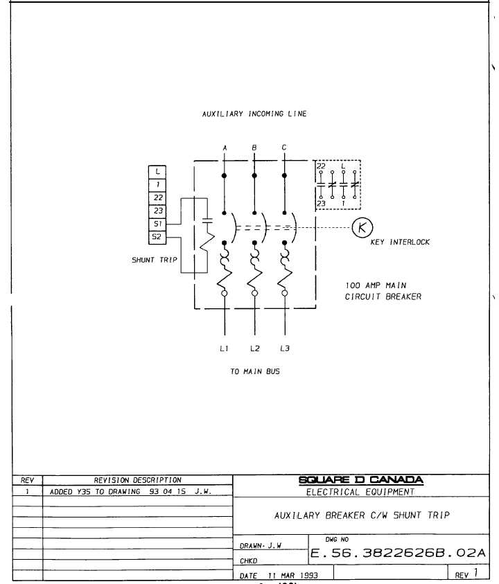
Auxilary Breaker c/w Shunt trip - TM-5-3895-374-24-1_130
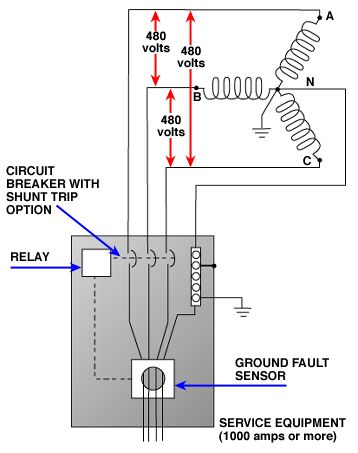
The main circuit breaker feeding the Siemens equipment must trip removing the 480VAC from the Siemens system. Additionally, the normally closed contacts must change state from a SHORT to an OPEN circuit. Only when the EPO button is pulled back out should it be possible to reset the main circuit breaker.
BR140ST | Eaton BR thermal magnetic circuit breaker | Eaton
shunt trip, and overcurrent trip switch warning (1)only qualified electrical personnel should be permitted to work on the equipment. (2)always de-energize primary and secondary circuits if a circuit breaker cannot be removed to a safe work location. (3)drawout circuit breakers should be levered (racked) out to the disconnect position.
Effectual Electric shunt trip nsx mccb Certified Products ...
Wiring Diagram For Shunt Trip Breaker Circuit, Diagram, Wire, The Unit, Chart. L. Lim Johnny. 317 followers. More information.

Square D QOB3901021 | Province Electric Supply
Installation Instructions for Shunt Trip for EHD, FDB, FD, HFD,. HFW,FWC Circuit Breakers, Molded Case Switches, and F-Frame Motor Circuit Protectors (HMCP).
Introduction Shunt Trip (Extended Range): A device designed ...
lps series shunt trip discoect switch r1 wiring diagram chicago, illinois 60631 3rd angle projection littelfuse® tolerance unless otherwise specified one place dec ± .25 [.01] fraction ± two place dec ± .100 [.004] angular ±1º revision drwg no. title drw date grams/piece finish good wt matl spec finish

8638 & 8639 Power Circuit S - Non-Reversing w/Shunt Trip ...
Square D Shunt Trip Breaker Wiring Diagram. Collection of square d shunt trip breaker wiring diagram. A wiring diagram is a simplified standard photographic depiction of an electric circuit. It shows the parts of the circuit as simplified forms, and also the power and also signal connections between the tools. A wiring diagram normally provides info concerning…

Elevator Shunt Trip Requirements and Codes | Fire Alarms Online
1 Aug 2021 — This is a very simple wiring diagram. You can see just there is an EPO or Emergency Power Off button is connected in series with the shunt trip ...
3VT2 Molded Case Circuit Breakers
6 ep.mersen.com • Fusible Shunt Trip Switch wiring diagraM – 120Vac cOntrOl interface Notes: 1. Tb-5 and Tb-9 must be dry (no voltage) normally open contacts from safety system 2 . If a surge protection option is selected, it will be corrected line to ground between the STS and fuses F1-F3
Installation Instructions for Series G N-Frame Circuit ...
Shunt Trip Wiring Diagram . June 12, 2019 1 0 . Wire the circuit breaker shunt trip motor mechanism br120st eaton type br brkr 20a 1 pole on a edb t80 wiring diagram 31 abb s5n second life square d qou2601042 province electric madcomics 3 200 amp 240 vac thermal magnetic siemens miniature amps ...

MCCB 】All you need to know about the accessories for MCCB
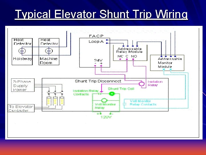
This diagram can help clear up the wiring in of fire alarm modules and relays. using an addressable relay module (FRM-1) to operate the shunt trip breaker directly. Labels: elevator equipment, elevator machine room, elevator recall, Waterflow, Backflow, PIV and OS&Y · Sprinkler Waterflow Flapper. On all of the fire systems I have wired, we put ...
What is the working principle of the UV and shunt tripping ...
Shunt Trip Breaker Wiring Diagram with EPO Button. In this post i am just tell you about wiring of single EPO button with shunt trip MCCB breaker. In industrial state, Electric operator duty is to operate the machinery and his duty is on the front of Main panel board. Aug 28, · A shunt trip is an accessory, not a type of breaker.

Shunt Trip Breaker Wiring Diagram, Connection, Circuit - ETechnoG
Shunt trip (MX) When the shunt trip (MX) receives a pulse-type or maintained voltage within specified tolerances it signals the circuit breaker to open. Show QR code for this page. Was this helpful?
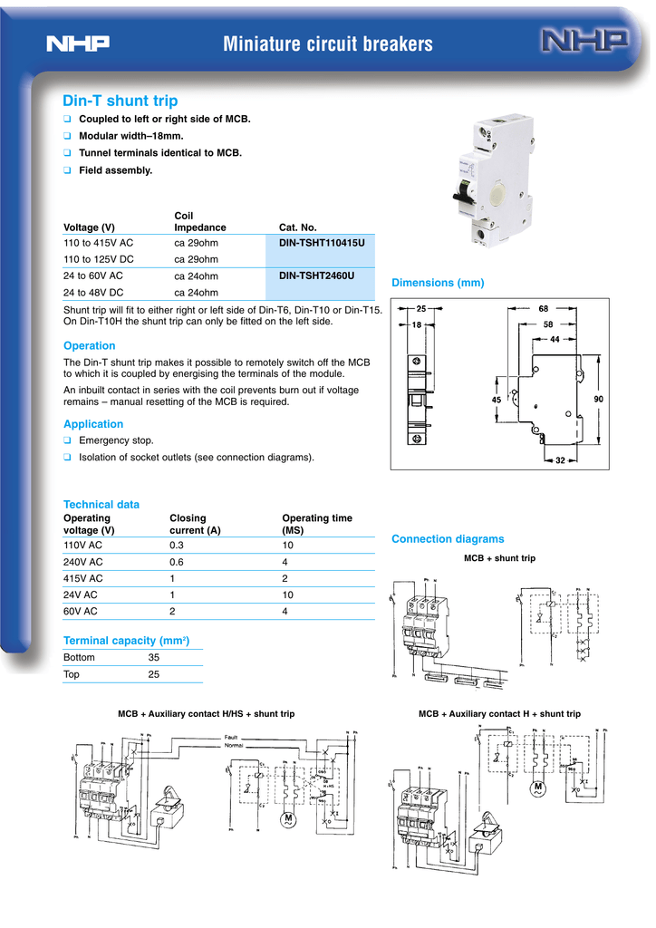
Din-T Shunt Trip
As stated previous, the lines in a Shunt Trip Breaker Wiring Diagramsignifies wires. Occasionally, the wires will cross. However, it doesn’t imply link between the wires. Injunction of 2 wires is generally indicated by black dot on the intersection of two lines. There will be primary lines which are represented by L1, L2, L3, and so on.
Understanding Demand
Shunt trip breaker wiring diagram. How it works the electrical current in a building passes through the system s circuit breaker unchanged if the current remains below a specified limit. It shows the elements of the circuit as simplified shapes as well as the power as well as signal connections in between the gadgets.

Elevator Shunt Trip Wiring Diagram | Fire Alarms Online

Motor Mechanism
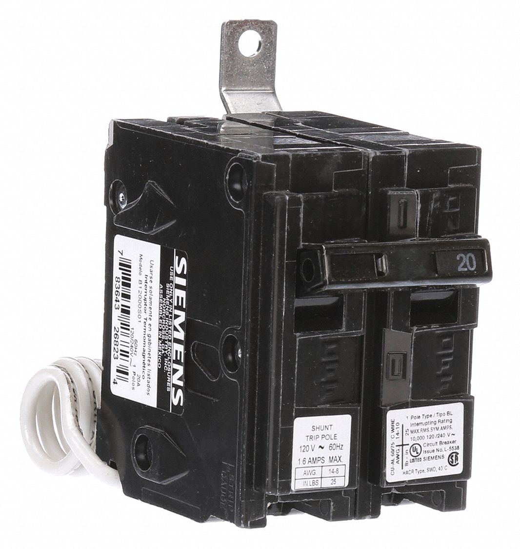
Miniature Circuit Breaker, Amps 20 A, Circuit Breaker Type Shunt Trip, Number of Poles 1

Wiring for Elevator Shunt Trip and Shunt Trip Power ...

Earth leakage circuit breaker Wiring diagram Relay Fault ...
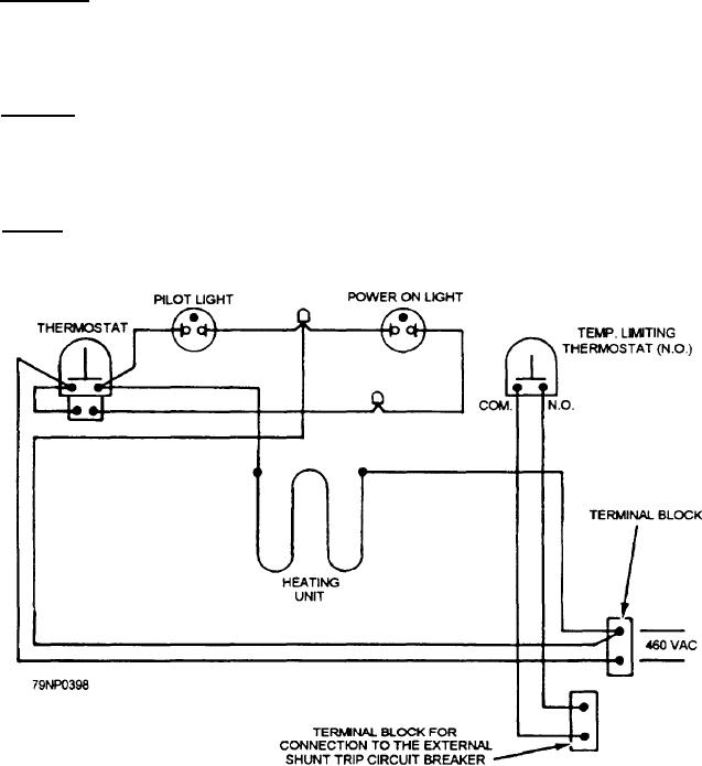
Figure 5-50.--Wiring diagram of the Mk 721 deep fat fryer.

GE Consumer & Industrial Electrical Distribution. Power Break ...

ASI SHT-220 MCCB Shunt Trip Module: Amazon.com: Tools & Home ...

Michael Lynn (walrus0910) - Profile | Pinterest

Motor Mechanism
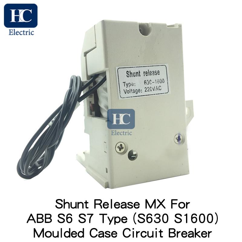
MX shunt trip release, Applicable for ABB S series S6 S7 ...

Circuit Breaker Schematic Diagram | Electrical Academia

China Shunt Release Shunt Trip Sht for Molded Case Circuit ...

lps series shunt trip disconnect switch | Manualzz

SOLVED: Do you have a wiring diagram for the square d - Fixya

Earth Leakage Relay Wiring and Connection Diagram - ETechnoG

Elevator Shunt Trip Requirements and Codes | Fire Alarms Online
Elevators Fire Alarm Systems Understanding Interface ...

Shunt Trip Breaker Wiring Diagram In Urdu & Hindi || How To ...


Comments
Post a Comment