40 pressure balancing loop diagram
The piping common to both the secondary and primary loops are the two tees and the common piping shown above. Rule "1" tells us to keep that common pressure drop very low. The reason being if there is nothing to stop it, the pressure drop in that pipe will cause a flow in the secondary circuit, even if the secondary pump is off. course of action included in the diagram. For example, an increase in “Production Pressure” may increase “Production Output,” but it may also increase “Stress” and decrease “Quality” 5. All balancing loops are goal-seeking processes. Try to make explicit the goals driving the loop.
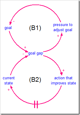
In causal loop diagrams, balancing loops are noted by a “B,” a “—,” or a scale icon in the center of a loop. The Structure of Balancing Loops. There is always an inherent goal in a balancing process, whether it is visible or not. The basic structure of a balancing loop involves a gap between the goal (or desired level) and the actual ...
Pressure balancing loop diagram
A causal loop diagram (CLD) explains the behavior of a system by showing a collection of connected nodes and the feedback loops created by the connections. One or more of the nodes represent the symptoms of the problem. The rest of the nodes are the causal chains causing the problem.. The simplest possible CLD contains two nodes. Below is an example from video 3 in The Dueling Loops Video Series. Jan 26, 2018 · The key is the continuous loop for equal volume output. Depending on the GPM output and how many sprayers I will increase the loop size to 3/4" copper instead of the minimum size of 1/2" to help with the balancing. We use PEX and copper around here but I always use copper for my showers- after the valve. I will also make sure a 3/4" valve is ... Loop Diagrams BAE 815 (Fall 2017) Dr. Zifei Liu ... Balancing loops can be automatic, or intentional policy. 14 Combination loops Births Dynamic behavior Deer population + R + Available food + B - ... Pressure for long-term fix-+ R Time Efforts quick fix Problem symptom Capacity of system
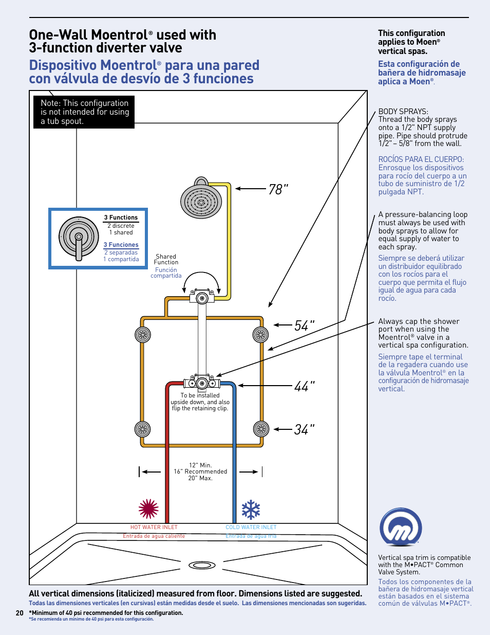
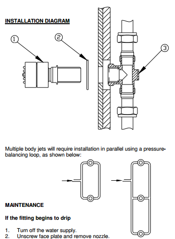
Pressure balancing loop diagram. The diagram below breaks out the functionality within the PIC, including the balancing, control, and differential pressure regulation: To understand the operation of the PIC, let's assume we have installed the device on a coil sized for 900 GPM as shown above. We have 34 PSIG entering the valve and 27 PSIG going out, meaning we have a 7 PSIG ... A pressure-balancing loop must always be used with body sprays to allow for equal supply of water to each spray. Maximum of 3 on 1 outlet. 2 body sprays may be operated as one function. Shower can be operated and personalized remotely with the U by Moen app, which is available for Android and iOS. Showerhead, Arm and Flange Handshower, Drop Ell ... Get a 3/4" shower valve; maybe a big tub valve with pressure balancing or thermostatic control. 2. Come out of the valve into the branch of a tee and make a loop of 3/4" connecting both ends of the tee. 8 NEW "SMART" PUMPS Speed varies without sensors High Efficiency ECM zElectronically Commutated Motor zA.k.a. DC Brushless Motor Integral VFD Sophisticated Electronics Residential to Light Commercial TYPE GPM HD (FT.) HP RPM HORIZ. IN-LINE 20 - 375 10 - 75 ¼ - 3 1760, 3500 END SUCTION 40 - 4,000 10 - 400 ⅓- 200 1160, 1760, 3500 VERTICAL IN-LINE 40 - 12,000 10 - 400 ¼ - 600 1160 ...
This is because it helps balance out the pressure drop between the various circuits. Manual balancing may require some touch. Whenever possible, JMP always recommends automatic flow balancing devices. However, when manual balancing must be used, many people use a hands-on balancing method.This means physically touching each riser pipe at start ... "Production Pressure"is inserted in between them. 10.A shortcut to determining whethera loop is balancing or reinforcing is to count the number of "o's" in the loop. An odd numberof "o's" indicates a balancing loop (i.e., an odd numberof U-turns keeps you headed in the opposite direction); an even num- d. Open-loop system e. Closed-loop system f. Feedback g. Controlled variable h. Manipulated variable 1.2 DESCRIBE the operation of a control loop diagram including the following components: a. Controlled system b. Controlled elements c. Feedback elements d. Reference point e. Controlled output f. Feedback signal g. Actuating signal h ... diagram, the standard control valves and balancing valves have been replaced with PICVs. Everything else stays the same. The loops are now balancing dynamically, meaning each loop is able to automatically and dynamically adjust for changes in the other loops since the PICV immediately responds to those differential pressure changes.
I'm making a pressure balancing loop. Due to piping req'ts, I am unable to position the loop inlet exactly in the middle of the non-fixture side. Is this okay, or do I need to make sure that the pipe distances from the inlet to the first spray (in each direction of the loop) are both exactly the same? Upvote. # 2. 07-27-03, 06:35 PM. bigbluedude2. Diagrams Can Have Multiple Loops Learning by doing Loop The more the NGO achieved results in its work, the better its reputation. People Loop The better its reputation, the higher quality people it was able to hire, boosting its capacity. Money Loop Also, the better its reputation, the more funds were available, boosting capacity. STUFF Variable Speed Pumping in Constant Volume or Pressure applications Use of VSP as throttling valve or control valve Pressure is maintained by impeller speed, so if pressure at pump needs to stay constant regardless of flow, may not be much advantage to VSP. Steep vs flat curves Domestic Water Booster If dominated by friction rather than lift, VFD is appropriate. vidual thermostatic, pressure-balancing and combination pressure balancing and thermostatic control valves for in-dividual fixture fittings." ASSE Standard 1017 is the standard for compliance when selecting a three-way mixing valve for a central distribution system. Be sure to evaluate the accuracy, minimum and maximum flow rates,
2
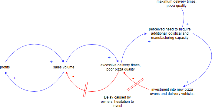
Edit this Diagram. Cause Loop Diagram Example - Growth and Investment. A Growth and Underinvestment structure is simply an elaborated Limits to Growth structure where the growth inhibitor is part of another Balancing Loop with an external standard and some delay.

A Systems Approach To Preventing And Responding To Covid 19 Eclinicalmedicine
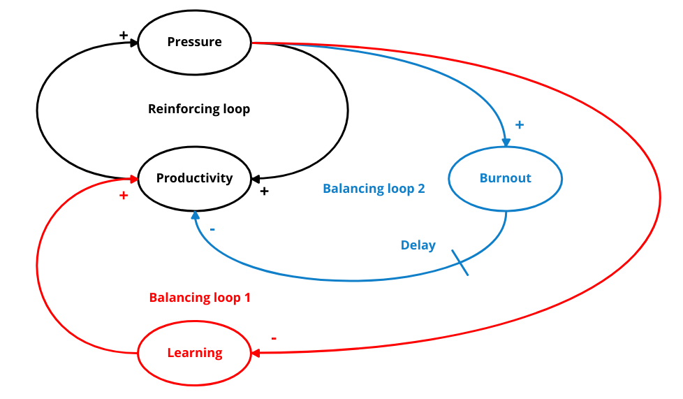
We differentiate between two kinds of feedback loops: balancing (or negative) feedback loops and reinforcing (or positive) feedback loops. The diagram above shows that if schedule pressure is high, then productivity is increased, which also increases the completion rate. This reduces the number of open tasks, which reduces the schedule pressure

Figure 3 Causal Loop Diagram Depicting The Role Of Education In Oxford Research Encyclopedia Of Environmental Science
When 2 or more body sprays are used, they need to be installed in a pressure balancing loop so that all of the sprays have equal flow, pressure and temperature. Typically, three sprays are used and installed in a vertical line. Ideal body spray placement is intended to cover the entire body with water no matter which way the person is facing.
Maybe This Isn T The Right Board For This But Ceramic Tile Advice Forums John Bridge Ceramic Tile
Figure 1: Typical block diagram for closed-loop control. Here, P denotes the plant, the system to be controlled, and C denotes the controller, which we design. Sensors and actuators are denoted y and f, respectively, and d denotes external disturbances. The − sign in front of f is conventional, for negative feedback. Reduce sensitivity.
Causal Loop Diagrams Little Known Analytical Tool
53. In the following diagram the P-V loop “A” is drawn for normal heart. The line “C” is the end- ... of systole) of two ventricular pressure-loops fall
Thinking In Systems
http://www.tilemasterga.com In this video I am showing setup and installation of CUSTOM KOHLER SHOWER SYSTEM using Thermostatic and Volume control valves. P...
One Wall Moentrol Moen Vertical Spa Mf2816 User Manual Page 20 24 Original Mode
Caleffi North America, Inc. 9850 South 54th Street Franklin, WI 53132 T: 414.421.1000 F: 414.421.2878 Dear Hydronic Professional, Welcome to the 2nd edition of idronics - Caleffi's semi-annual design journal for hydronic professionals.
What Is Causal Loop Diagram With Examples
simple balance flow diagram. The steam balance flow diagram can be accomplished in many different ways, such as a fully devolved document completed in Aspen software to a simple flow diagram completed with Microsoft Visio. The key point is to have a steam balance document for plant personnel. END RESULTS OF A STEAM BALANCE Implementing a ...
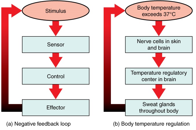
10 7 Homeostasis And Feedback Biology Libretexts
6. Name the loop: Give your loop a name! 7. Test and share your loops: Read the diagram as if you were telling a story. "As average com-muting times goes up, pressure to widen roads or add lanes goes up. As this pressure increas-es, the amount of new highway construction goes up. With more roads/lanes added, average commute time goes down.

Hydronic Balancing Wikipedia
Reinforcing Loop Balancing Loop Dynamic Behavior: Word of Mouth Sales Customers + + + Potential-Customers +-Graph for Customer 100,000 75,000 50,000 25,000 0 0102030405060708090100 Time (Month) Customer : Current
Pressure Balancing Loops Plumbing Zone Professional Plumbers Forum
Causal loop diagrams map the causal relationships between pairs of elements within a system and identify feedback loops. These loops can either be reinforcing (vicious cycle) or balancing (goal-seeking) and complex interactions between loops can lead to unintended consequences. The arrows in the diagram describe the directions of effect.

How To Install Multiple Shower Heads On One Manifold Without Losing Water Pressure Youtube
Re: Lack of Water Pressure from Body Sprays; Author: tlyoung99 (KY) Probably closer to 8 linear feet of 1/2 pipe due to the way I set-up the pressure balancing loops. I may have introduced too much pressure drop given the number of elbows and tees that I used. My pressure loop looks something like this: /---o---\ /---o---\
Pipeliq Pressure And Mass Flow Balance
Loop Diagrams BAE 815 (Fall 2017) Dr. Zifei Liu ... Balancing loops can be automatic, or intentional policy. 14 Combination loops Births Dynamic behavior Deer population + R + Available food + B - ... Pressure for long-term fix-+ R Time Efforts quick fix Problem symptom Capacity of system
Pressure Balancing Loops Plumbing Zone Professional Plumbers Forum
Jan 26, 2018 · The key is the continuous loop for equal volume output. Depending on the GPM output and how many sprayers I will increase the loop size to 3/4" copper instead of the minimum size of 1/2" to help with the balancing. We use PEX and copper around here but I always use copper for my showers- after the valve. I will also make sure a 3/4" valve is ...

Control Loops And Dynamics Spirax Sarco
A causal loop diagram (CLD) explains the behavior of a system by showing a collection of connected nodes and the feedback loops created by the connections. One or more of the nodes represent the symptoms of the problem. The rest of the nodes are the causal chains causing the problem.. The simplest possible CLD contains two nodes. Below is an example from video 3 in The Dueling Loops Video Series.
Double Shower Plumbing
Shower Pressure Balance Loop Question Ceramic Tile Advice Forums John Bridge Ceramic Tile

City Creek Plumbing Home Facebook

Why A Balancing Loop Can Help A System Correct Itself Shortform Books

Force Balance Principle An Overview Sciencedirect Topics

Structure Of Pressure Balance Loop Download Scientific Diagram
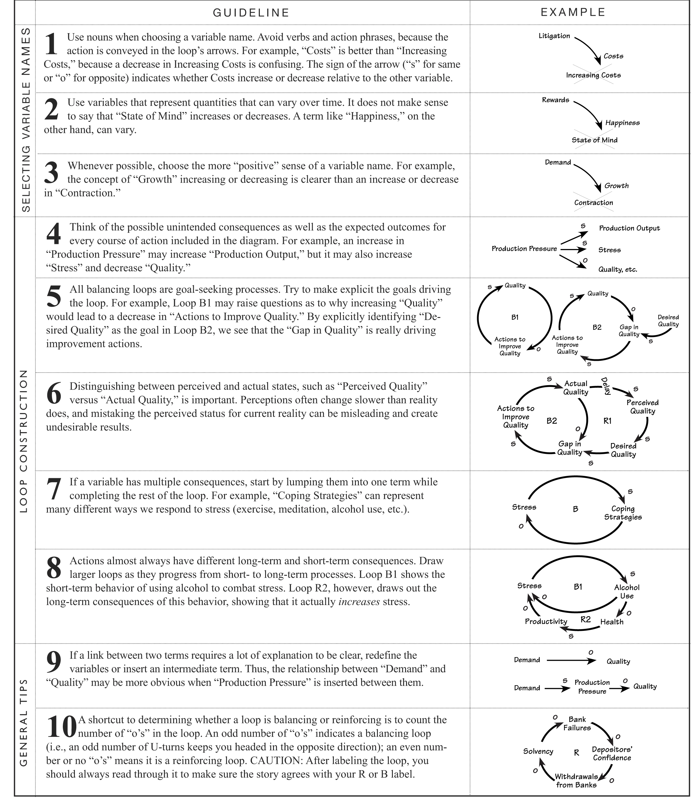
The Systems Thinker Guidelines For Drawing Causal Loop Diagrams The Systems Thinker

Balancing Loop With Delay Insight Maker
Pressure Transducer Sensor How It Works Futek
Pressure Loop For Two Sets Of Body Sprays Terry Love Plumbing Advice Remodel Diy Professional Forum
Pressure Balancing
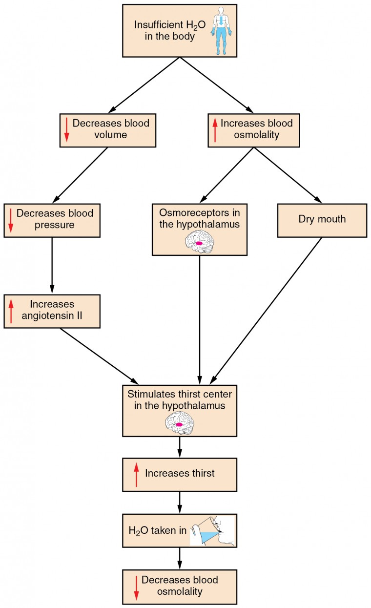
Water Balance Anatomy And Physiology Ii
Gold Square Ceiling Shower Head Set With 6 Shower Body Jets All In One Installation Manuals
Causal Loop Diagrams Springerlink
Koele Master Bath Remodel Ceramic Tile Advice Forums John Bridge Ceramic Tile
2

Industrial Plant Safety Improving Oil And Gas Well Safety
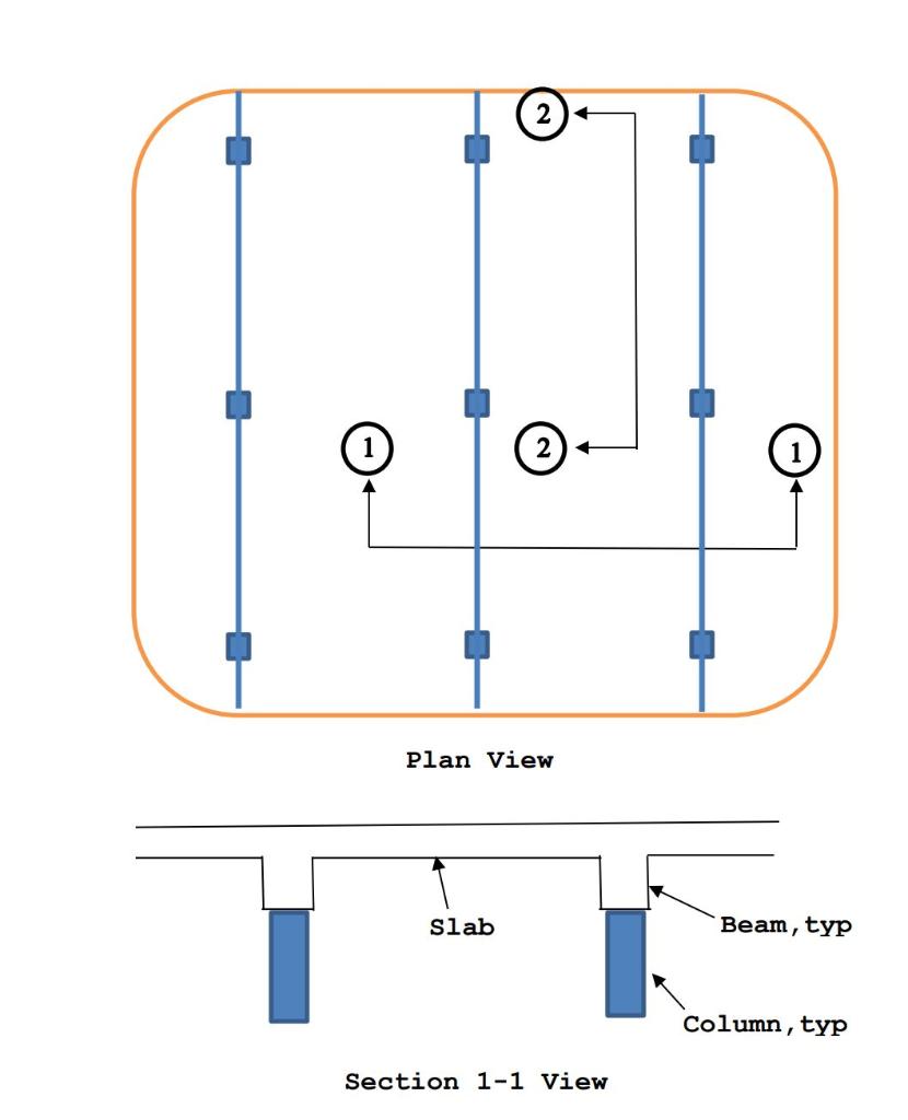
Solved For The Portion Of Reinforced Concrete Floor System Chegg Com
Drifting Goals Making Connections

Systems Thinking Primer Lv Yi
1

Example Of Balancing And Reinforcing Feedback Loops Diagram Adapted Download Scientific Diagram
Need Advice Pressure Balancing Loop Vs Terry Love Plumbing Advice Remodel Diy Professional Forum
System Thinking With Casual Loop Diagram Learn By Examples By Warren Lynch Medium
Pressure Balancing Loop Terry Love Plumbing Advice Remodel Diy Professional Forum


Comments
Post a Comment