38 use case context diagram
What is a use case diagram? In the Unified Modeling Language (UML), a use case diagram can summarize the details of your system's users (also known as actors) and their interactions with the system. To build one, you'll use a set of specialized symbols and connectors. An effective use case diagram can help your team discuss and represent: Context diagrams. A context diagram is a graphical representation of a system which must only use one process to represent the entire system and deliberately does not go into defining all the processes so as to prevent people getting bogged down in complex details at an early stage.
Step 2: Click on Open Libraries and select the appropriate category. It is advisable to use the templates in System Context Diagram Templates to get a picture of what you need to draw. Step 3: Next, drag the correct shapes and drop them onto the canvas to create the context diagram. To write into the form, double click on it.

Use case context diagram
Figure 6 represents the functional demand analysis of the middleware system as a use case diagram. Producers or managers use the two context aware service and event processing service functions ... The use case scenario, often represented by a sequence diagram, includes the coordination of several objects and classes, uses cases to help define messages (operations and information or data required-parameters) that connect objects together. The use of cases is an appropriate technique to evoke and document black-box functional requirements. A use case diagram is an excellent picture of the system context; it makes a good context diagram, that is, showing the boundary of a system, what lies outside of it, and how it gets used. It serves as a communication tool that summarizes the behavior of a system and its actors.
Use case context diagram. • Context diagrams can capture interactions • Use cases can capture user and patient experience • Combining these with conventional requirements analyses yields a better product The following example describes a medical device, but the methodology applies more broadly to all healthcare processes Page 3 INCOSE IW 2015 MBSE Workshop Use Case (Context) Diagrams: Suggested Notation Use Case Diagrams Downplay diagramming, Keep it short and simple Focus on text Do not focus on use case relationships Context diagram of the system Shows boundary What lies outside of it How it gets used Should be done in conjunction with an actor-goal list Alternative Actor Notation DFD diagram and Use case diagram are used to view the system from different perspective/angle. A graphical representation of the flow of data or information in a system or part of system. It consists of data flows, processes, sources, destinations and stores. Difference Between Use Case & Data Flow Diagram Use case diagrams are used to gather the requirements of a system including internal and external influences. These requirements are mostly design requirements. Hence, when a system is analyzed to gather its functionalities, use cases are prepared and actors are identified.
A popular form of the use-case diagram may help summarize the interaction of actors with the system. This diagram is called a top-level use-case diagram, but as it's very similar to a type of diagram that predates UML; often you'll see it called by its traditional name: context diagram. This type of diagram, shown in Figure 8-7, displays ... A context diagram is a top-level data flow diagram. So why not create one by first creating lower level diagrams vs lower level use cases? There is a huge difference between use cases and data flow diagrams. With use cases, the analyst never knows if he/she is done with analysis. This a BIG problem in ultimately creating a context diagram. A use case diagram consists of a use case and an actor. A use case represents a distinct functionality of a system, a component, a package, or a class. An actor is an entity that initiates the use case from outside the scope of a use case. The name of an actor or a use case must be meaningful and relevant to the system. Use case diagram is a behavioral UML diagram type and frequently used to analyze various systems. They enable you to visualize the different types of roles in a system and how those roles interact with the system. This use case diagram tutorial will cover the following topics and help you create use cases better. Importance of use case diagrams
We can create a use case diagram in two ways: Right-click on the selected element and select " Create a diagram... ". Click on the " Create a UML/BPMN diagram... " button in the application toolbar. Step 3. Select "Use Case diagram" in the left-hand list. We can see that the context field is already completed. Use Case Diagram Objective • Built in early stages of development • Purpose •Specify the context of a system •Capture the requirements of a system •Validate a systems architecture •Drive implementation and generate test cases •Developed by analysts and domain experts How do use case diagrams fit in? This applies also to use case descriptions. Unlike the context diagram, the use case diagram does provide some visibility into the system. Each oval inside the system boundary box represents a use case. The use case diagram shows the interactions of the system with its users and some connections between internal system operations, albeit at a high level of abstraction. Use case diagram: One of the Unified Modeling Language diagrams. They also represent the scope of the project at a similar level of abstraction. - Use Cases, however, tend to focus more on the goals of 'actors' who interact with the system, and do not specify any solution.
Sunset & Clouds, Harlow Green, Gateshead, Tyne & Wear, England.
Purpose of Use Case Diagram Use case diagrams are typically developed in the early stage of development and people often apply use case modeling for the following purposes: Specify the context of a system Capture the requirements of a system Validate a systems architecture Drive implementation and generate test cases
Putting Systems Analysis “Into Context” using the Context Diagram
Differences between 'Context diagram' and 'Use case diagram': a. Use case diagram illustrates logical relationships and dependencies between use cases in detail. b. Use case diagram provides a visibility into the system. Context diagram is a single process for summarizing the whole system. Use case diagram is a summary diagram as well.
Solved Given the following use case diagram, draw the | Chegg.com
A context diagram is a high-level, informal view of three things: the system you're going to be gathering requirements for, the things that need to interact with the system (use case experts call these things external entities ), and a brief note about the interaction between each thing and the system (#3 is optional).
Use Case Diagrams (S8 CS) | Lecture Notes
Unlike the context diagram, the use case diagram does provide some visibility into the system. Each oval inside the system boundary box represents a use case. The use case diagram shows the interactions of the system with its users and some connections between internal system operations, albeit at a high level of abstraction.
Use case context diagram for the proposed KBRM framework (Karadsheh et... | Download Scientific Diagram
The project context diagram links a work package to organizations, functions, services, processes, applications, business or data entities, and technologies that will be added, withdrawn, or modified by the project. The project context diagram is also a useful tool in the management of application portfolios and for initiating a project.
All You Need to Know About Use Case Modeling | by Warren Lynch | Medium
Assignment help: Compare and contrast a context diagram (using data flow diagram (DFD) modeling) and a use case diagram (using unified modeling language (UML))? We ensure that all your instructions are followed to the letter. You are able to choose the level of interest; professional, college, or high school.

Unesco World Heritage Site, English Heritage, Chesters Roman Fort, Hadrian's Wall, Northumberland, England.
What is a Use Case Diagram? A use case diagram is a dynamic or behavior diagram in UML. Use case diagrams model the functionality of a system using actors and use cases. Use cases are a set of actions, services, and functions that the system needs to perform. In this context, a "system" is something being developed or operated, such as a web site.
UML replacement for context diagram - Stack Overflow
In the past I have used a use case diagram to create a context diagram, using actors for external systems and people and a class with the <<system>> stereo type to represent the system under development. You're right that there isn't a system stereotype in the list provided but I just type it in.
What Comes Before The Use Case Model?
A use case diagram is an excellent picture of the system context; it makes a good context diagram, that is, showing the boundary of a system, what lies outside of it, and how it gets used. It serves as a communication tool that summarizes the behavior of a system and its actors.

Adalaj Stepwell: Plan and Elevation
The use case scenario, often represented by a sequence diagram, includes the coordination of several objects and classes, uses cases to help define messages (operations and information or data required-parameters) that connect objects together. The use of cases is an appropriate technique to evoke and document black-box functional requirements.
Use case diagrams are UML diagrams describing units of useful functionality (use cases) performed by a system in collaboration with external users (actors).
Figure 6 represents the functional demand analysis of the middleware system as a use case diagram. Producers or managers use the two context aware service and event processing service functions ...
Northrop Grumman SR-78 Aurora blueprint

JPQUESTIONS ANATOMY EDITION: INDORAPTOR SKULL

SAKURAI / Introduction to M-Theory and SuperStrings / The Final Visualization Extending And Interacting Into Twenty Six Dimensions
Including processes that are external to the system in Use Case diagram and DFD - Software Engineering Stack Exchange

Image from page 86 of "Breeder and sportsman" (1882)

Roma – I Fori Imperiali (1995-2008). The Forum of Augustus. Excavations & Related Studies (2004-2008) / Foro di Augusto - L’Aula del Colosso (Forum of Augustus - The Hall of Colossus).

SAKURAI - An Emergent Behavior of Collective Quantum Systems.
System context diagram - Wikipedia

History-of-Pandemics-Deadliest-3 alt
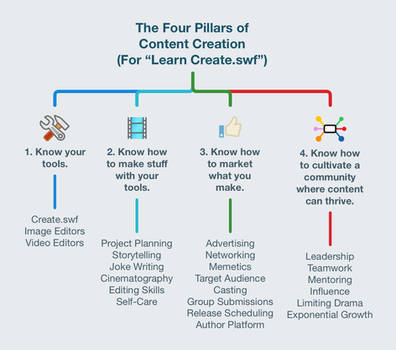
The Four Pillars of Walfas Content Creation 2021

Use case diagram for online book store - heavenlybells.org
Northrop Grumman SR-78 Aurora blueprint call 2
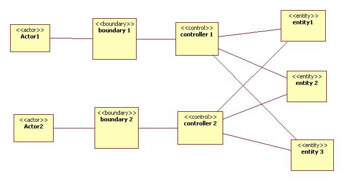
The Entity-Control-Boundary Pattern

Psychohistory: An Octahedral Approach

Architecture, Church Of Saint martin, Saran, Central-Val Et Loire, French Republic.

Image from page 204 of "Personal identification; methods for the identification of individuals, living or dead" (1918)

Computed tomography (CT) scan showing a thick bladder wall ...
Solved guse Case diagram, a. draw the context diagram (10 | Chegg.com

Unesco World Heritage Site, English Heritage, Chesters Roman Fort, Hadrian's Wall, Northumberland, England.
UML Use Case Diagram Tutorial | Lucidchart
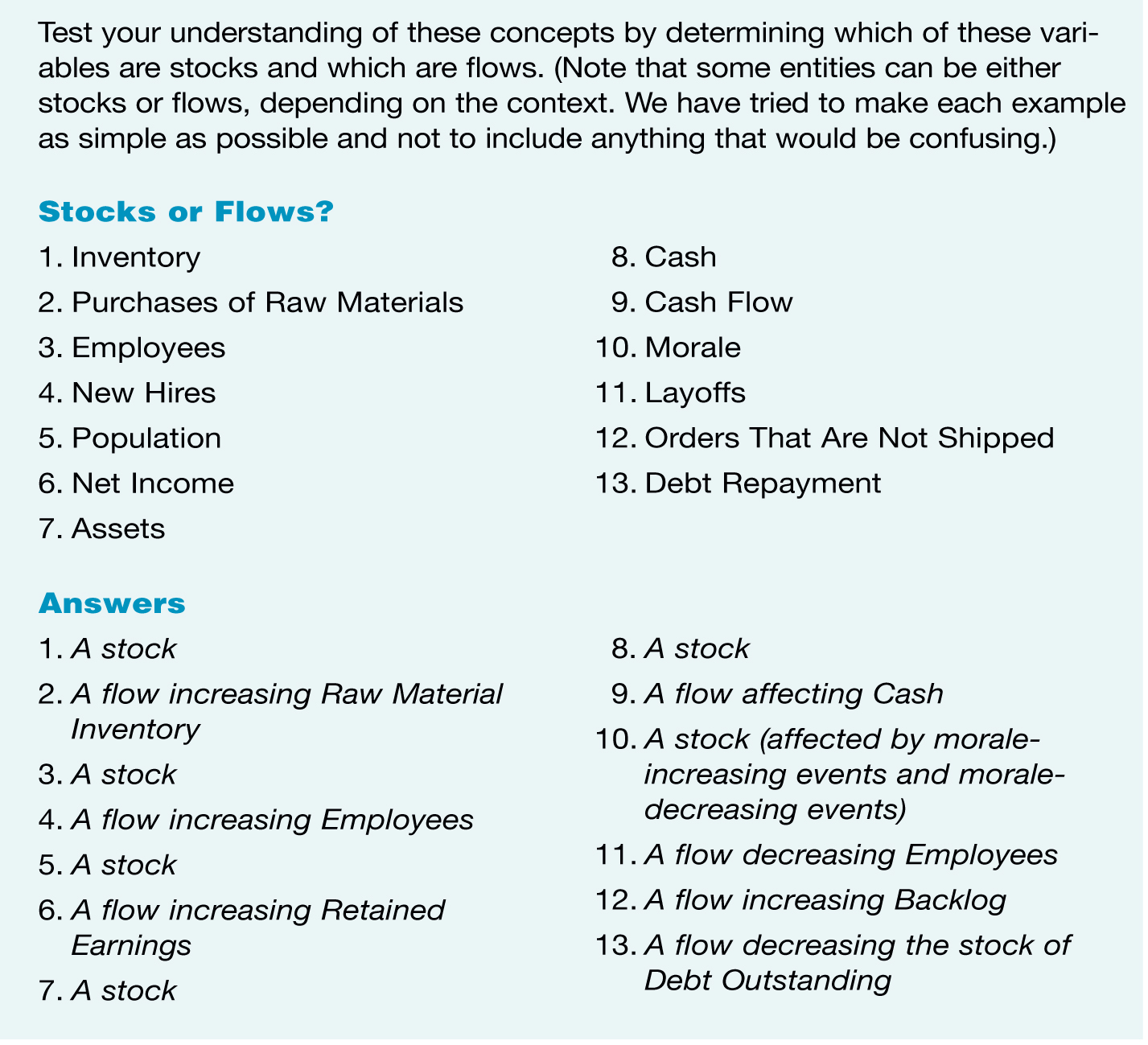
The Systems Thinker – Step-By-Step Stocks and Flows ...

SAKURAI / THE ELEVENTH DIMENSION UNIVERSE VIEW / M-THEORY GALAXIES EDGE MULTIDIMENSIONAL VIEWING

Ermitage rupestre de San Pelayo
SysML FAQ: What is a Use Case diagram (UC)?

The vibrational states of a string gives rise to the SAKURAI GRAVITON shown captured in full dimension. DSS00320 M1-9

SAKURAI COSMOLOGICAL PARALLEL INFLATION

The symbolism of the four cardinal directions..... Cardinal directions in Chinese language: their cultural, social and symbolic meanings.


Comments
Post a Comment