41 iron carbon equilibrium diagram
General construction The phase ... and the carbon content can be read off this dual diagram in which the stable system iron-graphite (dotted lines) and the meta-stable system iron-carbide (solid lines) are shown together, (Figure 1). The closeness of the equilibrium lines which ... Iron-Cementite diagram is not a true equilibrium diagram, since equilibrium means no change of phase with time, however long it may be. Graphite is more stable form of carbon. Cementite is a metastable phase, which decomposes to graphite if given long periods of time.
The iron-carbon diagram provides a valuable foundation on which to build knowledge of both plain carbon and alloy steels in their immense variety. Fig. 1. The iron-carbon diagram. It should first be pointed out that the normal equilibrium diagram really represents the metastable equilibrium between iron and iron carbide (cementite).

Iron carbon equilibrium diagram
Although it is heterogeneous, these phases behave like homogeneous pure bodies. Steel is between 0 and 2.06 mass percent of carbon. Cast iron is between 2.06 ... Accomplishing excellence in the technical education and act as repository and leader for disseminating state-of-the art knowledge and expertise in the field of materials technology and other relevant / emerging branches of engineering and technology concomitant with industrial growth of the ... The Iron-Carbon Equilibrium Diagram · Firstly, there is the A1, temperature at which the eutectoid reaction occurs (P-S-K), which is 723°C in the binary diagram.
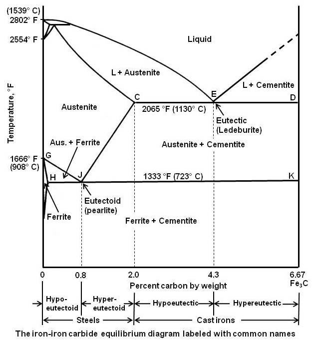
Iron carbon equilibrium diagram. Iron-Carbon Equilibrium Diagram. Engineering Materials. A modified iron-carbon diagram is shown in Fig. 13.2. The point A (1539° C) on the diagram is the melting point of pure iron. The point E shows the solubility limit of carbon in gamma iron at 1130° C (1.7%). The iron carbon alloys containing upto 1.7% carbon are called steels and those ... The Equilibrium Diagram: A Simple Explanation for Prospective Ground Engineers of the Iron‐Carbon Constitution Diagram - Author: Norman Macleod 1 – Austenite and Ferrite · 3 – Austenite and Cementite Martensite (non equilibrium BCT phase from quench of γ) BCC Orthorhombic Iron/Carbon Phase Diagram Iron shows a eutectic with Carbon allowing for a lower melting alloy Body Centered Tetragonal. 6. 7. 8 Carbon content can be reduced by reaction with oxygen and stirring. 9. 10 Eutectoid Steel Pearlite. 11
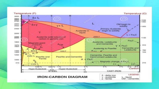
The iron -carbon phase diagram in Fig 2 actually shows two diagrams namely (i) the stable iron-graphite diagram (red lines), (ii) and the metastable Fe-Fe3C diagram. Cementite is metastable, and the true equilibrium is to be between iron and graphite (C). February 14, 2020 - The part of iron-carbon alloy system diagram between pure iron and an interstitial compound, iron carbide (Fe3C), containing 6.67 percent carbon by weight is called iron-iron carbide equilibrium diagram. It may be noted that though it is called as equilibrium diagram, it is not a true equilibrium ... This iron carbon phase diagram is plotted with the carbon concentrations by weight on the X-axis and the temperature scale on the Y-axis. The carbon in iron is an interstitial impurity. The alloy may form a face centred cubic (FCC) lattice or a body centred cubic (BCC) lattice. It will form a solid solution with α, γ, and δ phases of iron. The iron-carbon diagram assumes a constant cooling of the metals. If the metal is slowly cooled down, coarse grains are formed. If the metal is cooled down quickly, fine-grained metal is the result. The type of metal grain determines the strength properties. Coarse grain has a lower strength, but can be made finer-grained and therefore stronger ...
Iron Carbide Equilibrium Diagram/ Material Science / Engineer's AcademyHello Everyone Welcome To AIM AMIEIn this videos we have covered the Iron Carbon Equil... The Fe-C phase diagram is a fairly complex one, but we will only consider the steel part of the diagram, up to around 7% Carbon. University of Tennessee, Dept. of Materials Science and Engineering 2 MSE 300 Materials Laboratory Procedures Phases in Fe-Fe3C Phase Diagram ¾ α-ferrite - solid solution of C in BCC Fe • Stable form of iron at ... Principles of Physical Metallurgy by Prof. R.N. Ghosh,Department of Metallurgy and Material Science,IIT Kharagpur.For more details on NPTEL visit http://npt... Iron Carbon phase diagram. On this diagram, the carbon percentage is shown on the x-axis and temperature on the y-axis. This figure shows the Iron Carbon Equilibrium Diagram. In this diagram, the lines indicate the boundaries where the alloy changes its phase. The different phases or mixture of phases occur in different areas enclosed by these ...
Image from page 456 of "Transactions" (1871)
Cementite is a chemical compound of carbon with iron and is known as iron carbide (Fe3C). Cast iron having 6.67% carbon is possessing complete structure of cementite. Free cementite is found in all steel containing more than 0.83% carbon. It increases with increase in carbon % as reflected in Fe-C Equilibrium diagram. It is extremely hard.

Image from page 41 of "Transactions" (1871)
Iron-Carbon Phase Diagram with Detailed Explanation: If the percentage of the carbon is in the range of 0 to 2.11 % then it is called Steel and if the percentage of carbon is in the range of 2.11 to 6.67% then it is called Cast iron. As the carbon content increases, it produces more Iron-Carbide volume and that phase will exhibit high hardness.
Muddiest Point- Phase Diagrams II: Eutectic ...
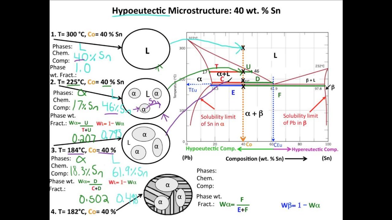
Carbon Equilibrium Diagram. Before solidification (freezing) can occur the temperature must fall to a point on the lines AB or BC The Iron Carbon eutectic contains the equivalent of 4.3% Carbon. The "frozen" eutectic has a composition of Austenite solid solution (Of composition E) and Iron Carbide.
Iron Carbon Alloys - Metallurgy - Engineering Reference ...
The Fe – C diagram (also called the iron – carbon phase or equilibrium diagram) is a graphic representation of the respective microstructure states of the alloy iron – carbon (Fe-C) depending on temperature and carbon content. To explain this diagram, an introduction about metal structures and pure iron must be done.

Image from page 65 of "Transactions" (1871)
November 8, 2015 - Outline Introduction Cooling curve for pure iron Definition of structures Iron-Carbon equilibrium phase diagram – Sketch The Iron-Iron Carbide Diagram - Explanation The Austenite to ferrite / cementite transformation Nucleation & growth of pearlite Effect of ...
fe-c diagram
Although it is heterogeneous, these phases behave like homogeneous pure bodies. Steel is between 0 and 2.06 mass percent of carbon. Cast iron is between 2.06 ...Date: 27 February 2019

Image from page 64 of "Transactions" (1871)
Ch. 5: Equilibrium Phase Diagrams and the Iron-Carbon System. Composition is fixed. Not much usage to materials area. Shows the phase change occurring within a material of particular composition, as the material is cooled. This is where the Equilibrium Phase Diagrams are derived.

Image from page 511 of "Transactions" (1871)
Cast iron having 6.67% carbon is possessing complete structure of cementite. Free cementite is found in all steel containing more than 0.83% carbon. It increases with increase in carbon % as reflected in Fe-C Equilibrium diagram. It is extremely hard. The hardness and brittleness of cast iron is believed to be due to the presence of the cementite.

Image from page 504 of "Transactions" (1871)
Cementite or iron carbide, is very hard, brittle intermetallic compound of iron & carbon, as Fe 3 C, contains 6.67 % C. It is the hardest structure that appears on the diagram, exact melting point unknown. Its crystal structure is orthorhombic. It is has low tensile strength (approx. 5,000 psi), but high compressive strength.

Image from page 54 of "Transactions" (1871)
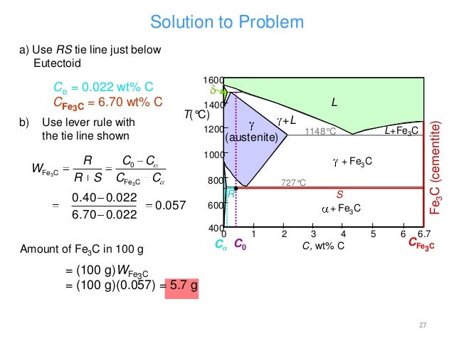
Review Fe-C phase diagram • 2 important points-Eutectoid (B): γ⇒α+Fe 3C-Eutectic (A): L ⇒γ+Fe 3C Fe 3 C (cementite) 1600 1400 1200 1000 800 600 400 0 12 3 4 5 66.7 L γ (austenite) γ+L γ+Fe 3C α+Fe 3C α + γ L+Fe 3C δ (Fe) C o, wt% C 1148°C T(°C) α 727°C = Teutectoid A R S 4.30 Result: Pearlite = alternating layers of αand Fe ...
Iron iron carbide equilibrium phase dia gram
phase diagram has not been well established---in the temperature, composition, and pressure ranges not related directly to iron and steel making. In the present evaluation, the assessed stable Fe-C (graphite) and metastable Fe-Fe3C (cementite) equilibrium phase diagrams for 0 to 25 at.%

Image from page 70 of "Transactions" (1871)
June 1, 2012 - Dr. Dmitri Kopeliovich Iron-carbon phase diagram describes the iron-carbon system of alloys containing up to 6.67% of carbon, discloses the phases compositions and their transformations occurring with the alloys during their cooling or heating.

Image from page 494 of "Transactions" (1871)
There is more to the iron-carbon phase diagram than related in the backbone. In particular, there is some nomenclature that I avoided in the main text but that is important for understanding other writings about iron and steel. So let's start with a phase diagram that contains maximal information:

microestructure of annealing hypoeuctoid steel
Crystal Structures, Equilibrium Phases and the Iron-Carbon Phase Diagram The material properties of Irons and Steels are highly dependent on their Carbon content. This is because Carbon content changes both the crystal structures of an iron-carbon alloy and the resulting microstructures that form.

Image from page 474 of "Transactions" (1871)
This amount of carbon is decisive for the quality and properties of the steel. The iron-carbon phase diagram is an equilibrium diagram of the two elements. With its help, the relationship between the carbon content and the temperature is derived. On this basis, the phase composition can be ...

Image from page 73 of "Transactions" (1871)
The Iron-carbon phase or equilibrium diagram is an overall study of iron, carbon, and their alloys and how they act under the various equilibrium conditions. In this blog, we studied these aspects of the equilibrium diagram and also how phase transformation depends upon the temperature conditions.
Practical Maintenance » Blog Archive » The Iron-Iron ...
Answer: The iron-carbon diagram (also called the iron-carbon phase or equilibrium diagram) is a graphic representation of the respective microstructure states depending on temperature (y axis) and carbon content (x axis). The melt essentially cools via the austenite to ferrite phases - i.e. from...

Image from page 459 of "Transactions" (1871)
Iron Carbon Equilibrium Diagrams - Engineering Notes ... Cementite is an inter-metallic compound of Iron and Carbon. It is a hard and brittle material. Austenite. Exists Between 1390°C and 910°C. Has a BCC structure. Also known as Gamma iron. Pearlite.

Image from page 56 of "Transactions" (1871)
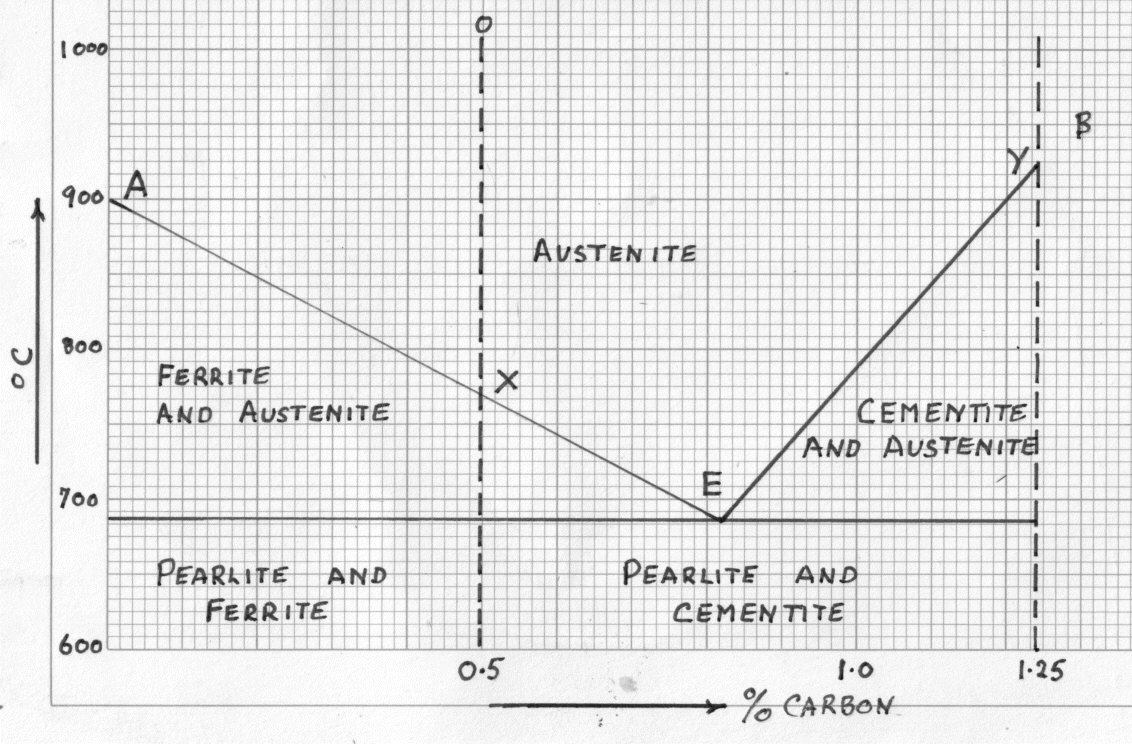
IRON CARBON EQUILIBRIUM DIAGRAM, TTT DIAGRAM AND HEAT TREATMENT 1. IRON CARBIDE DIAGRAM TTT DIAGRAM & HEAT TREATMENT By: Ankit Saxena 2. IRON-C phase diagram 3. From previous fig of FE-C diagram 4. • Hypo-eutectoid steels: Steels having less than 0.8% carbon are called hypo-eutectoid steels (hypo means "less than").

Carbon Diffusion in an Iron Pipe
https://www.youtube.com/LogicalVideosdotorgIRON CARBON EQUILIBRIUM DIAGRAMiron carbon equilibrium diagramiron carbon diagramiron carbon equilibrium diagram p...

Image from page 68 of "Bulletin - United States National Museum" (1877)
1. IRON-CARBON EQUILIBRIUM DIAGRAM PRESENTED BY: ADITI RANA A2305316090 B.Tech (IT-2X) 2. In their simplest form, steels are alloys of Iron (Fe) and Carbon (C). The Fe-C phase diagram is a fairly complex one, but we will only consider the steel and cast iron part of the diagram, up to 6.67% Carbon. 3.
PPT - Chapter 4 Equilibrium Phase Diagrams and The Iron ...
The Iron-Iron Carbide Diagram. The part of iron-carbon alloy system diagram between pure iron and an interstitial compound, iron carbide (Fe 3 C), containing 6.67 percent carbon by weight is called iron-iron carbide equilibrium diagram. It may be noted that though it is called as equilibrium diagram, it is not a true equilibrium diagram, since ...
Iron Carbon Equilibrium Diagram
The Iron-Iron Carbide Diagram. The iron-carbon composite scheme diagram portion between plain iron and an interstitial compound, iron carbide (Fe3C), comprising 6.67 percent by weight is called iron-iron carbide balance diagram. It may be observed that although it is called as a diagram of equilibrium, it is not a real diagram of equilibrium ...

Image from page 507 of "Transactions" (1871)
Maximum solubility of carbon is 2.1% at 1150 0 c. 𝛿 - Iron:-Above 1400 0 c γ iron changes to 𝛿 - Iron, this is B.C.C. structure. Maximum solubility of carbon is 0.08% at 1495 0 c. Cementite:-In Iron carbon alloys, if carbon is excess of the solubility limit form Iron carbide or cementite (Fe 3 c). Orthorhombic structure . Pearlite:-

Image from page 503 of "Transactions" (1871)
The Iron-Carbon Equilibrium Diagram · Firstly, there is the A1, temperature at which the eutectoid reaction occurs (P-S-K), which is 723°C in the binary diagram.

Image from page 34 of "Transactions" (1871)
Accomplishing excellence in the technical education and act as repository and leader for disseminating state-of-the art knowledge and expertise in the field of materials technology and other relevant / emerging branches of engineering and technology concomitant with industrial growth of the ...

Sunset & Clouds, Harlow Green, Gateshead, Tyne & Wear, England.
Although it is heterogeneous, these phases behave like homogeneous pure bodies. Steel is between 0 and 2.06 mass percent of carbon. Cast iron is between 2.06 ...

Image from page 44 of "Bulletin - United States National Museum" (1877)

Image from page 584 of "Twentieth century hand-book for steam engineers and electricians, with questions and answers .." (1905)

Influence of Alloying Elements on Steel Microstructure ...

Image from page 475 of "Transactions" (1871)
IRON CARBON EQUILIBRIUM DIAGRAM - YouTube


Comments
Post a Comment